PVfarmer
Senior Member
- Location
- Newport County, Rhode Island, USA
Hello, this is my first question on this forum. I've found so many good answers here I'm a little confused!
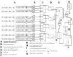
I have a rough draft (very rough some would probably say) of a one line drawing if anyone wants to see it.
About the inverters: 60kW total (which is also 60kVA...?, because the PF of the inverters is =1. Or...1 / 0.8 leading?0.8 lagging)
Consisting of four 15000TL inverters:
Output phases / line connections 3 / 3-N-PE
Nominal AC voltage 480 / 277 V WYE
The grid is 12470Y/7200.
We have single phase, 7200V to 120/240 service now, 200 amps.
It goes through one 25kVA xfmr, which is 208 amps, 4% over the service level. Not quite enough.
So...60kW of inverter power, when the current single phase (7200V) inverter on the pole is 25kVA, isn't going to sit well, as in, if we turned that PV on, BOOM, not good at all!
The lowest amperage 480/277 service offered is 100A.
The 12.47 to 480/277 xfmrs seem to be VERY expensive.
It seems like it would be less $$ if the POCO went with three 7200 --> 480/277 transformers, but I don't know their prices yet on everything.
BUT...60kW doesn't match up easily with common sizes of xfmrs.
20kVA or 60kVA xfmrs aren't common. 25kVA, 30, and 75 are.
Going by things I've seen here, there are different ways to do this. I'm looking for simplest.
The POCO is OK with a line side connection, so....
how important to both the grid people AND the overall balance of both system and grid is it to match the xfmrs and inverters as closely as possible?
SO...which one here? If they are OK with not going for a whole 100A of xfmrs on the pole, A seems "low", C seems "high" or "hot", B seems like it may be best match overall and for 100A service, but B is another 100+ panels and a lot more paperwork.
A. Four 15000TLs - 60kW - 72A ---> three 25kVA xfmrs?
B. Four 20000TLs - 80kW - 96A ---> 3 30kVA xfmrs? (96A being that 4% under thing again)
C. Five 15000TLs - 75kW - 90A ---> 3 25kVA xfmrs?
D. Three 24000TLs - 72kW - 87A ---> 3 30kVA?
E. Totally over the top- TWO 24000TLs with the same amount of panels as A, for a 1.66 ratio of panel watts/inverter output. ---> One 50kVA transformer. 4% under again. File that under "so crazy it might work", I have to try a simulation with that one. Hmm.
F. other?
They aren't kidding when they say these inverters are "flexible"!
There was a comment in this forum about using two larger and one smaller transformers for the grid connection, not sure how one would "balance" that to the grid's benefit.
I also saw something about having a Delta between the two wyes to...trap harmonics?
Also something about "wild leg" wiring for 120/240.
The going from 480/277 Y to 120/240 part seems straightforward enough, any thoughts there would be appreciated too.
This, for instance?
http://www.temcoindustrialpower.com/products/Transformers_-_General/HT0213.html
or...this?
http://www.temcoindustrialpower.com/products/Transformers_-_General/HT0193.html
We're getting another xfmr to supply the current 120/240 wiring off of the PV output- the PV will be going in line side. If we do this right, with some batteries, there won't be a drop of power used all year.
But then...too much inverter will sit there wasting power at night, which adds up eventually.
Too little is of course also a bad idea, but...
whew, it really gets complicated!
Thanks, if anyone can help out here.
These inverters seem like you could program them to put out a few kWs while you sleep and THEN turn on the coffee maker at 7AM!
http://www.wseas.org/multimedia/journals/power/2013/035702-208.pdf
2. Step-up transformers for conventional PV plants
The cost of the step-up transformer for a PV plant can be evaluated as a composition of four contributions, namely:
? initial cost
? cost of the energy wasted due to transformer
overloads
? cost of energy wasted due to transformer
efficiency
? cost of energy wasted due grid instability
2.3 Energy losses due to transformer efficiency
The power wasted due to no load and copper losses
during the k-th interval can be computed through the
following equation, assuming constant the
amplitude of the inverter output voltage:
(equation won't paste correctly)
")