gar
Senior Member
- Location
- Ann Arbor, Michigan
- Occupation
- EE
150307-0847 EST
grasfulls:
If your original motion sensors were Triac ouput, then for now we shall assume that the Triacs were inadequate for the load which consisted of the magnetic transformer and its LED loads.
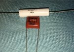
Your modified circuit with the sensors connected to control an electro-magnetic relay is a good solution. You can select a relay of an appropriate size for your load. The relay coil of any reasonable size relay will not overload the the Triac switches in typical sensors. Your only problem with driving the relay coil is providing sufficient load to keep the Triac on. A 2000 ohm 20 or 25 W Ohmite resistor in parallel with the relay coil is probably sufficient. This wasted power is no problem because the lights are not on for a long time.
You do need to make sure the output relay is large enough for the load.
You don't need separate AC supplies for different parts of your circuit.
.
grasfulls:
If your original motion sensors were Triac ouput, then for now we shall assume that the Triacs were inadequate for the load which consisted of the magnetic transformer and its LED loads.
Your modified circuit with the sensors connected to control an electro-magnetic relay is a good solution. You can select a relay of an appropriate size for your load. The relay coil of any reasonable size relay will not overload the the Triac switches in typical sensors. Your only problem with driving the relay coil is providing sufficient load to keep the Triac on. A 2000 ohm 20 or 25 W Ohmite resistor in parallel with the relay coil is probably sufficient. This wasted power is no problem because the lights are not on for a long time.
You do need to make sure the output relay is large enough for the load.
You don't need separate AC supplies for different parts of your circuit.
.
")