Is a voltage doubler economic?

ruxton.stanislaw

Senior Member
Location
Arkansas
Occupation
Laboratory Engineer
My LOL was for practicality at 150 kW, did not run a design but think one would need cubic YARDs of capacitor sizes.
I can envision the capacitors/diode arrays will be huge. However, we have room for it because land and bricks here are dirt cheap. The main thing is whether the capacitors are more or less expensive than the transformer (and the associated losses over decades or at least the service life of the capacitors). We are technically exporting energy in this plan (with a revenue grade meter), so every bit of heat lost counts.
 

synchro

Senior Member
Location
Chicago, IL
Occupation
EE
Where did the need for 1.5 kVDC come from? Are you intending to use PV inverters but would be supplying their DC input from another source? If so, are you intending to tie the inverter output to a higher grid voltage than 400/230V, because a 1500 VDC inverter would be capable of that. If the grid you want to drive is at 400/230V then I think 1500 VDC capability would provide little or no advantage in your intended application, because the PWM would be throttling down the AC output swing quite a bit from its maximum capability. But a higher DC voltage would still be useful in reducing the DC conductor sizes and/or losses in a PV application.

The other thing with PV inverters is that they are designed to have what's essentially a current source drive (but with a limited voltage capability) from the strings of PV panels. Feeding a PV inverter from a low impedance DC source might impact the operation of the inverter. If the inverter has internal MPPT control that has been activated, then its behavior could be unpredictable with a constant voltage and low impedance input. I've also seen some descriptions of inverter PV architectures where the MPPT control of the DC-DC converter is intentionally interacting with the control of the PWM on the inverter output stages to do the overall control functions. If you intend to use PV inverters, you could do some experiments to see how they react with a low impedance source.

If you are considering some other type of inverter than those designed for PV applications, then you can ignore most of the above comments.


By the way, among its other issues, the voltage regulation of a voltage multiplier like a doubler will be relatively poor, and a tripler will be even worse in that regard.
 

Jpflex

Electrician big leagues
Location
Victorville
Occupation
Electrician commercial and residential
Is it economic to design a voltage doubler to convert 400Y/230 V to 1.5 kV DC or would a traditional transformer and rectifier be more cost effective? Assume 150 kW; 100 A on the DC load.
I’m not familiar with “voltage doublets” beyond transformers ding this. Can anyone explain more on this? Is this still using coils and impresses voltage?
 

ruxton.stanislaw

Senior Member
Location
Arkansas
Occupation
Laboratory Engineer
Where did the need for 1.5 kVDC come from? Are you intending to use PV inverters but would be supplying their DC input from another source? If so, are you intending to tie the inverter output to a higher grid voltage than 400/230V, because a 1500 VDC inverter would be capable of that. If the grid you want to drive is at 400/230V then I think 1500 VDC capability would provide little or no advantage in your intended application, because the PWM would be throttling down the AC output swing quite a bit from its maximum capability. But a higher DC voltage would still be useful in reducing the DC conductor sizes and/or losses in a PV application.

The other thing with PV inverters is that they are designed to have what's essentially a current source drive (but with a limited voltage capability) from the strings of PV panels. Feeding a PV inverter from a low impedance DC source might impact the operation of the inverter. If the inverter has internal MPPT control that has been activated, then its behavior could be unpredictable with a constant voltage and low impedance input. I've also seen some descriptions of inverter PV architectures where the MPPT control of the DC-DC converter is intentionally interacting with the control of the PWM on the inverter output stages to do the overall control functions. If you intend to use PV inverters, you could do some experiments to see how they react with a low impedance source.

If you are considering some other type of inverter than those designed for PV applications, then you can ignore most of the above comments.


By the way, among its other issues, the voltage regulation of a voltage multiplier like a doubler will be relatively poor, and a tripler will be even worse in that regard.
Thanks for your input. We are going to be testing several different options, for example the ABB PVS800 and 150kW SMA Sunny Highpower PEAK3 Inverter. In some cases, they can handle more than 100 A (I put that as a simple figure to work with a base design) or in other cases, we will have a current shunt. We are also toying with the idea of our own IGBT based designs, but my gut is that the certification processes required for the grid operator will be a pain.
 

synchro

Senior Member
Location
Chicago, IL
Occupation
EE
Thanks for your input. We are going to be testing several different options, for example the ABB PVS800 and 150kW SMA Sunny Highpower PEAK3 Inverter. In some cases, they can handle more than 100 A (I put that as a simple figure to work with a base design) or in other cases, we will have a current shunt. We are also toying with the idea of our own IGBT based designs, but my gut is that the certification processes required for the grid operator will be a pain.

Do those inverters have galvanic isolation between the DC input and AC output, for example by using a high frequency transformer within a DC-DC converter? Without such galvanic isolation, there is likely to be some substantial AC common mode voltages between the DC input and AC output, depending on how the inverter is implemented. And then if you power the PV inverter with a ground referenced DC supply you might get some problematic currents when you tie the inverter outputs to a ground referenced grid. Of course, a line frequency transformer with an ungrounded secondary could be used to drive a rectifier and that would provide the required isolation, and it could also boost the voltage.

A spec sheet for the 150kW SMA Sunny Highpower PEAK3 Inverter you mentioned lists a "Maximum operating input current" of 180A and a "Maximum input short-circuit current" of 325A. That should be straightforward to satisfy when the inverter is supplied with an appropriately sized array of PV panels, because they have a limited output current. But that might be more challenging when supplied from your 400Y/230V source.

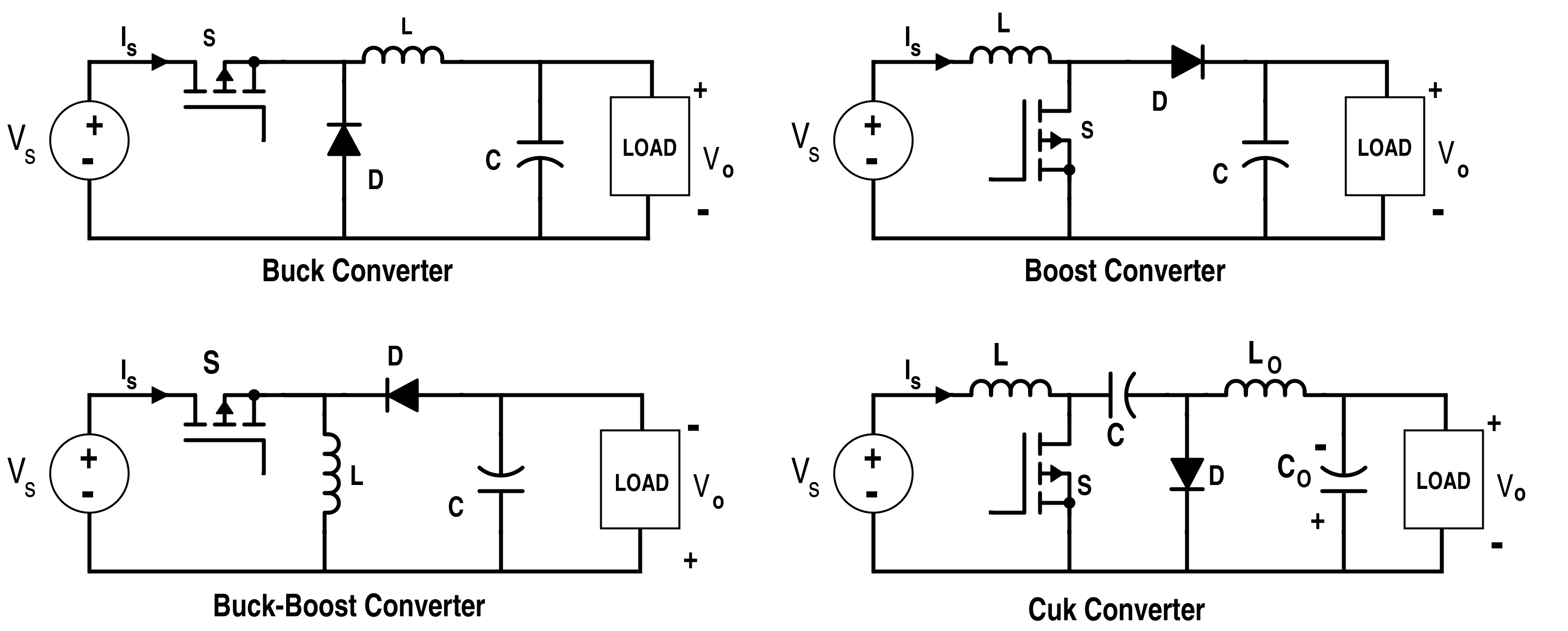
Just a thought, but one possible way to limit the short circuit DC current is to insert a buck-boost DC-DC converter in the DC supply. As shown below, in the buck-boost converter there is no direct connection for current to flow from input to output. The transistor and diode are in series between the source and load, but they do not conduct at the same time and so this limits the amount of current through a short circuit on the output. The buck-boost converter shown below is inverting, meaning that the output DC voltage polarity is negative for a positive input. I don't think this would be a significant issue for the application at hand. A non-inverting version requires an additional transistor and diode.

4A-Converter-in-Equilibrium-2.png
 
Last edited:

junkhound

Senior Member
Location
Renton, WA
Occupation
EE, power electronics specialty
S is for switch.

Symbol shown is N channel Metal Oxide Semiconductor Field Effect Transistor,, commonly called MOSFET. Can alo be implemented with regular transistor or IGBT (Insulated Gate Bipolar Transistor)

Typical operation is 20 kHz (above human hearing so you odont hear a magnetostriction whine as inductor cycles) to 1 MHz, typically run at 100 kHz

For those unfamiliar, to say convert 100 Vdc to 50 Vdc, S claoses for say 5 microseconds, current builds in L and thru the load and charging capacitor. Then S is open for 5 us, incuctor L current decays thru the load and diode, C help smooth out voltage. Inductor current builds to steady state and cycles repeat. There are many different control chips to perform this control function.

There are literally HUNDREDS of variations of these circuits, many drive ferrite transformers for step up or step down.
 
Last edited:

synchro

Senior Member
Location
Chicago, IL
Occupation
EE
By the way, I often sat next to Slobodan Ćuk (pronounced "Chook") in a Control Systems course in college. A few years later he invented what became known as the Ćuk converter, which is the 4th switching supply circuit in my post above.
 

ruxton.stanislaw

Senior Member
Location
Arkansas
Occupation
Laboratory Engineer
There is a good video by EEVblog covering the original voltage doubler/tripler concept ("Cockcroft-Walton Multiplier"):

As for this project, similar variants of the DC-DC converter schematics that @synchro has shared are likely the direction we are headed in. Thanks everyone!
 

synchro

Senior Member
Location
Chicago, IL
Occupation
EE
There is a good video by EEVblog covering the original voltage doubler/tripler concept ("Cockcroft-Walton Multiplier"):

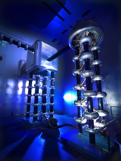
Some years ago I was on a tour with a group of the Fermilab particle accelerator complex. On entering the room where the accelerator starts the guide asked "Does anyone know what this is?". I hesitated and waited for someone else to say something. But nobody did, and so I said it's a Cockcroft-Walton voltage multiplier. The tour guide jokingly said "Oh, a wisenheimer". We both laughed. Those really high voltage versions use spark gaps instead of rectifiers.


FT_20120821_pic1_cockcroft_walton.jpg

https://history.fnal.gov/historical/accelerator/so_long.html
 
Top