[
but in your calculation of short circuit sync.motor, MVAsc = MVA/0.23
1. so what the x''=15.38%, x1=15.38%, x0= 15.38%
are used for? why you are using 0.23 (23%) ?
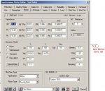
I got the 0.23 off the screenshot of the motor data input form. I see now that it doesn't match your data: Xd?% = 15.38%. MVAsc for positive and negative sequence should be 2MW/(pf x 0.1538). Assume nameplate pf is 0.95, then MVAsc1&2 = (2MW / (0.95 x 0.1538) = 13.69 MVA. But check the data, if the 15.38% is given based on 2000kW rating, use that.
2. correct me if I wrong, but should the zero sequence MVA of motor (MVAsc0) be .....0?
in a figure before, motor will contribute to earth fault through the netral connected to earth?
My apologies! You are correct. I had it wrong. I had to go back to Moon Yuen's original paper on the MVA method. (He was my mentor when I started out. He would be quietly correcting me about now). We
do include the motor in the MVA method zero sequence diagram. Why would the motor data include Xo=15.38% if that was not the case! So motor?s MVAo = 13.69 MVA, same as the positive and negative sequence. (Typical induction motor?s zero sequence impedance is about ? the positive. I am not certain about synchronous motors. Check your data.).
By the way...please refer to fig.(DIAGRAM A,B) (Attach), are there something wrong of calculation MVAsc of 3 winding trafo?
The 3-winding calculation looks correct, provided all the winding impedances are based on the 10 MVA rating. If the 7% Zpt and Zst for the secondary and tertiary windings are based on the 5 MVA or 3 MVA winding rating, you need to convert them to a common 10 MVA base.
By the way?Your sketch also shows motor Locked Rotor current of 453.5%. This translates to an Xd? = 1/4.535 = 0.22 or 22%.
I?ll stop posting before I make more errors. Good luck.