That is a "flaw" in the system. It depends on initial engineering for load calculations and requires care be taken when adding future loads but it is Code permissible. IF you want to avoid that possibility you can put a 400 amp main at your meter and size all accordingly and accept the added expense.
You are using an out of date browser. It may not display this or other websites correctly.
You should upgrade or use an alternative browser.
You should upgrade or use an alternative browser.
Properly configuring layout for 400 A service/meter socket with 3 downstream panels
- Thread starter gcammerata
- Start date

- Status
- Not open for further replies.
gcammerata
Member
- Location
- Pennsylvania
- Occupation
- Engineer / Contractor / Energy Consultant
Got it Augie! I really appreciate the detailed explanations!
VirutalElectrician
Senior Member
- Location
- Mpls, MN
- Occupation
- Sparky - Trying to be retired
Is the shop used for livelihood?
When designing for situations like this, I prefer a separate stand alone power pedestal. That way if the shop or house burns, you don't lose power to the other.
When designing for situations like this, I prefer a separate stand alone power pedestal. That way if the shop or house burns, you don't lose power to the other.
gcammerata
Member
- Location
- Pennsylvania
- Occupation
- Engineer / Contractor / Energy Consultant
Unfortunately they will only allow one meter setting
gcammerata
Member
- Location
- Pennsylvania
- Occupation
- Engineer / Contractor / Energy Consultant
Is the shop used for livelihood?
When designing for situations like this, I prefer a separate stand alone power pedestal. That way if the shop or house burns, you don't lose power
gcammerata
Member
- Location
- Pennsylvania
- Occupation
- Engineer / Contractor / Energy Consultant
Not sure what you mean by livelihood. There will be a bathroom and small kitchenette inside the shop.
Tulsa Electrician
Senior Member
- Location
- Tulsa
- Occupation
- Electrician
Looking at the drawing for the separate structure( house). You plan on a wire way then tap to two different locations than the through( wire way) is located.
Would 225.32 apply.
Have you considered the GEC lay out for that structure
Would 225.32 apply.
Have you considered the GEC lay out for that structure
electrofelon
Senior Member
- Location
- Cherry Valley NY, Seattle, WA
I think there is a better way. Why not put the meter on a pedestal outside near the transformer, then use 230.40 exception #2 to feed the two panels at the house with two 200A sets, and then 230.40 exception #3 (mentioned by Augie) to feed the shop. Everything is service conductors so only three wire needed.So would it make sense to go from the fused disconnect to a trough to pull the other feeds from or is there a better way?
hillbilly1
Senior Member
- Location
- North Georgia mountains
- Occupation
- Owner/electrical contractor
I wanted to do that when I built my house to feed my shop too (commonly called a farm service) but the poco wouldn’t let me. They said the TVA wouldn’t let them connect to that type of service.I think there is a better way. Why not put the meter on a pedestal outside near the transformer, then use 230.40 exception #2 to feed the two panels at the house with two 200A sets, and then 230.40 exception #3 (mentioned by Augie) to feed the shop. Everything is service conductors so only three wire needed.
gcammerata
Member
- Location
- Pennsylvania
- Occupation
- Engineer / Contractor / Energy Consultant
Can you tell me what the GEC layout is? I am not familiar.Looking at the drawing for the separate structure( house). You plan on a wire way then tap to two different locations than the through( wire way) is located.
Would 225.32 apply.
Have you considered the GEC lay out for that structure
Tulsa Electrician
Senior Member
- Location
- Tulsa
- Occupation
- Electrician
A better way to put it would have been a GES .Can you tell me what the GEC layout is? I am not familiar.
Separate structure supplied by a feeder would require one even if your feeder has an EGC. When sizing you bonding conductors the rules change a bit when sizing.
I would review 225.31 as well.
This is why I had ask about locations. With 225.32 it takes you to 250.32.
Something to consider with your lay out.
gcammerata
Member
- Location
- Pennsylvania
- Occupation
- Engineer / Contractor / Energy Consultant
I like this idea. If I did this, the meter socket would need to be capable of handling 3 feeds on the load side. My meter socket is a Milbank U1129-0-DTE. Attached is a pic of the interior. Can you tell if this meter socket Is capable of handling a distribution lug that has three 250 KCMIL lugs per leg? And if so, any help specifying the proper lug would be helpful. Thank you again for your help!I think there is a better way. Why not put the meter on a pedestal outside near the transformer, then use 230.40 exception #2 to feed the two panels at the house with two 200A sets, and then 230.40 exception #3 (mentioned by Augie) to feed the shop. Everything is service conductors so only three wire needed.
Attachments

gcammerata
Member
- Location
- Pennsylvania
- Occupation
- Engineer / Contractor / Energy Consultant
Also, as a followup question, in the scenario described above, where would the neutral be bonded to ground? It seems like it would need to be at all 3 panel locations.. is that correct? Because we don't have a main panel/sub panel setup, where the only bonding would be at main panel.
electrofelon
Senior Member
- Location
- Cherry Valley NY, Seattle, WA
Correct, you would have 3 service disconnects, each with a MBJ.Also, as a followup question, in the scenario described above, where would the neutral be bonded to ground? It seems like it would need to be at all 3 panel locations.. is that correct? Because we don't have a main panel/sub panel setup, where the only bonding would be at main panel.
Regarding the three terminals in the meter socket, I am not familiar with that exact socket, but the class 320 sockets we get here just come with studs and you provide the lugs you need.
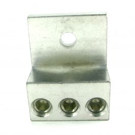
3S250TP Triple Barrel Wire Lugs Turn Prevent Rib (250 kcmil (4/0 AWG)-6 AWG)
Three barrel tin plated aluminum wire lug for use with 250 kcmil (4/0 AWG)-6 AWG wire. This single barrel lug can be used with aluminum or copper wire. NEMA mounting holes and spacing; this is not a NEMA tested part,
 www.mechanicallugs.com
You can also get stackable crimp on lugs.
LarryFine
Master Electrician Electric Contractor Richmond VA
- Location
- Henrico County, VA
- Occupation
- Electrical Contractor

wwhitney
Senior Member
- Location
- Berkeley, CA
- Occupation
- Retired
So if you provide your own lugs that may be larger than the options available from the manufacturer, what rule governs how much clearance (air space) you need to leave between lugs and between each lug and the metal enclosure?Regarding the three terminals in the meter socket, I am not familiar with that exact socket, but the class 320 sockets we get here just come with studs and you provide the lugs you need.
Cheers, Wayne
electrofelon
Senior Member
- Location
- Cherry Valley NY, Seattle, WA
The license professional who is doing the installation will decide.So if you provide your own lugs that may be larger than the options available from the manufacturer, what rule governs how much clearance (air space) you need to leave between lugs and between each lug and the metal enclosure?
Cheers, Wayne
wwhitney
Senior Member
- Location
- Berkeley, CA
- Occupation
- Retired
But surely there is an NEC or UL rule that you need to follow?The license professional who is doing the installation will decide.
For example, 312.11(A)(3) specifies at least 0.5" air space between the live parts and the enclosure (for 250V and under, or 600V and under if certain conditions are met). So that answers my question for that clearance. If the stacked lugs pictured in post #36 got closer than 1/2" from the front cover, they would not be allowed.
But what about between live parts? I'm thinking that the triple lugs you pictured are fairly wide, so the air space between lugs would be reduced.
Cheers, Wayne
electrofelon
Senior Member
- Location
- Cherry Valley NY, Seattle, WA
I think you know my philosophy Wayne, that I am vehemently opposed to this nanny state/dumbing down /"brother -in-law proofing" of the code where electricians are becoming mere "installers" and can't make any judgements based on actual conditions in the field to make things work. I'll have to double check, but I'm pretty sure the US constitution has a clause about freedom to use lugs as necessary in the field to suit conditionsBut surely there is an NEC or UL rule that you need to follow?
For example, 312.11(A)(3) specifies at least 0.5" air space between the live parts and the enclosure (for 250V and under, or 600V and under if certain conditions are met). So that answers my question for that clearance. If the stacked lugs pictured in post #36 got closer than 1/2" from the front cover, they would not be allowed.
But what about between live parts? I'm thinking that the triple lugs you pictured are fairly wide, so the air space between lugs would be reduced.
Cheers, Wayne
 .
.- Status
- Not open for further replies.