PV backfeed + existing load breaker sizing

Status
Not open for further replies.

tallgirl

Senior Member
Location
Great White North
Occupation
Controls Systems firmware engineer
I have had those questions on a couple of somewhat unbalanced systems (Sunny Boys in phase to neutral configuration where a multiple of three inverters was not possible); I answered them by saying the inverters match grid voltages so there is no significant voltage imbalance, and that satisfied them.

They don't match grid voltage. The inverter will raise the voltage all the way back to the transformer, by however much it takes, to push however much power they have to push.
 

jaggedben

Senior Member
Location
Northern California
Occupation
Solar and Energy Storage Installer
I don't --

So did you mistype in post 33? That's where you said this...

This problem seems limited to supply-side interconnections, ... [etc.]

but the second a load is added to a line-side tap, it's no longer a line-side tap, no?

I'm not even sure if I agree with that, but I don't see how it affects the neutral in the case we're discussing (a single 120V inverter connected to a 240/120 split-phase system).
 

jaggedben

Senior Member
Location
Northern California
Occupation
Solar and Energy Storage Installer
Okay...???

diagram2.gif

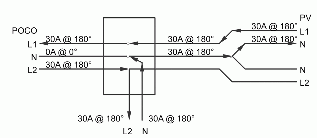
Smart$ I'm going to go out on a limb here...

Here's a marked up version of your diagram. diagram2 edited.gif


Seems to me you made a wrong assumption at the place marked with red. Since there's no PV generation on L2, it should be at 0 degrees to the the utility.

And if red is wrong, then it follows that pink is wrong, and that we have a problem at orange.
 

GoldDigger

Moderator
Staff member
Location
Placerville, CA, USA
Occupation
Retired PV System Designer
They don't match grid voltage. The inverter will raise the voltage all the way back to the transformer, by however much it takes, to push however much power they have to push.

But because the impedance of the grid is so low, the change in voltage will be relatively small except on the local service and transformer unless the PV power is a significant fraction of the total load on POCO.
 

tallgirl

Senior Member
Location
Great White North
Occupation
Controls Systems firmware engineer
But because the impedance of the grid is so low, the change in voltage will be relatively small except on the local service and transformer unless the PV power is a significant fraction of the total load on POCO.

Don't underestimate how much a PV system can change that local service. I've seen rural systems where the voltage swing between when the system was producing power, and when it was consuming power, is close to 40 volts line to line.
 

ggunn

PE (Electrical), NABCEP certified
Location
Austin, TX, USA
Occupation
Consulting Electrical Engineer - Photovoltaic Systems
They don't match grid voltage. The inverter will raise the voltage all the way back to the transformer, by however much it takes, to push however much power they have to push.
But that amounts only to whatever voltage drop is in the lines (voltage rise at the inverter terminals) to the interconnection, which if the system is designed correctly is minuscule. Twice the power on a phase does not mean twice the voltage on the line. The inverter is a virtual current source and doesn't need to raise voltage over the line voltage to push current; if the wires to the transformer were superconductors with no voltage drop/rise at all, the inverter would still supply power to the grid at exactly the same voltage as the interconnection.
 

ggunn

PE (Electrical), NABCEP certified
Location
Austin, TX, USA
Occupation
Consulting Electrical Engineer - Photovoltaic Systems
Don't underestimate how much a PV system can change that local service. I've seen rural systems where the voltage swing between when the system was producing power, and when it was consuming power, is close to 40 volts line to line.
True enough and that can be a problem if there is a lot of voltage drop in the transmission lines out to the end of a branch of the grid. Imbalance is not the only way it can cause trouble, though; even a balanced PV system can be problematic in situations like that.
 

jaggedben

Senior Member
Location
Northern California
Occupation
Solar and Energy Storage Installer
The inverter is a virtual current source and doesn't need to raise voltage over the line voltage to push current;

This may be partly semantic, but to my understanding that's exactly what the inverter needs to do. A load conducts current from an inverter instead of the utility because the potential from the inverter is slightly higher where that load is connected (or vice versa). A load that is conducting current from both sources does so because the voltage potential is the same from both sources where the load is connected. An inverter powers the loads closest to it first, precisely because it encounters more impedance in the lines to loads that are farther away.

if the wires to the transformer were superconductors with no voltage drop/rise at all, the inverter would still supply power to the grid at exactly the same voltage as the interconnection.

If the super conductors had no voltage drop at all, then basic physics such as Ohm's law wouldn't be operating and this would be a different type of universe.
 

ggunn

PE (Electrical), NABCEP certified
Location
Austin, TX, USA
Occupation
Consulting Electrical Engineer - Photovoltaic Systems
This may be partly semantic, but to my understanding that's exactly what the inverter needs to do. A load conducts current from an inverter instead of the utility because the potential from the inverter is slightly higher where that load is connected (or vice versa). A load that is conducting current from both sources does so because the voltage potential is the same from both sources where the load is connected. An inverter powers the loads closest to it first, precisely because it encounters more impedance in the lines to loads that are farther away.


If the super conductors had no voltage drop at all, then basic physics such as Ohm's law wouldn't be operating and this would be a different type of universe.
Superconductors do exist, just not at temperatures feasible for utility conductors, and in them there is no voltage drop. Ohm's Law is still in force, and in this universe, too.

An inverter does not power loads closest to it preferentially; it does not discriminate between local loads and loads outside the meter. It's all just a massively parallel circuit. An inverter is a current source and it depends on the grid being a voltage source to keep everything stable.
 

jaggedben

Senior Member
Location
Northern California
Occupation
Solar and Energy Storage Installer
Superconductors do exist, just not at temperatures feasible for utility conductors, and in them there is no voltage drop. Ohm's Law is still in force, and in this universe, too.

Point conceded. But the voltage on the inverter side still has to be higher than the voltage on the utility side for energy to flow back to the utility.

An inverter does not power loads closest to it preferentially;

Sure it does. The loads that the inverter powers are those which have the least amount of impedance between them and the inverter, for which my shorthand is 'closest'.

If your statement was true then net-metering wouldn't work.
 

GoldDigger

Moderator
Staff member
Location
Placerville, CA, USA
Occupation
Retired PV System Designer
Point conceded. But the voltage on the inverter side still has to be higher than the voltage on the utility side for energy to flow back to the utility.

But it will only be higher by the amount of the IxR voltage drop in the wiring between the inverter and the service disconnect. At that point any additional IxR drop on the POCO side will just raise the voltage within POCO and not cause the inverter to go that much "higher than POCO". A subtle point, but one which affects the impact of large scale PV on other users of that part of the distribution network.


Sure it does. The loads that the inverter powers are those which have the least amount of impedance between them and the inverter, for which my shorthand is 'closest'.

If your statement was true then net-metering wouldn't work.

Ahem. If a certain amount of current (power) is available from the inverter, it will leave the inverter. Where it goes from there does not really matter as far as net metering is concerned.
Either it will go all the way to power your neighbor's loads and at the same time power from POCO will also flow in through the meter to power your loads and the meter will measure the difference (a condition that could not be detected unless you can watch individual electrons) or only the net current will flow through the meter and be counted by POCO.
The results are indistinguishable. It is a basic parallel circuit of two sources and two or more loads, one on your side of the meter and one on the POCO side of the meter.

If you put a large wire impedance between your local loads and the service wiring, does that mean that the inverter output will go out through the meter to other loads instead? No.

I admit that to some extent it is just two ways of looking at the same situation. The big difference between them is how well that view will serve you in understanding other things that are happening. :)
 

ggunn

PE (Electrical), NABCEP certified
Location
Austin, TX, USA
Occupation
Consulting Electrical Engineer - Photovoltaic Systems
Point conceded. But the voltage on the inverter side still has to be higher than the voltage on the utility side for energy to flow back to the utility.

No, it doesn't. The fact that the voltage is higher at the terminals of an inverter is a result of the current flow, not the cause of it. An inverter would work just fine with superconductors connecting it to the grid with no voltage rise whatsoever. It's a current source, not a voltage source; the current it puts out is independent of the impedance of the load it sees and hence the voltage drop in the conductors feeding the load.

Sure it does. The loads that the inverter powers are those which have the least amount of impedance between them and the inverter, for which my shorthand is 'closest'.

If your statement was true then net-metering wouldn't work.

Yes it would, and does. In fact, the impedance of the grid as seen by the inverter is orders of magnitude lower than the impedance of your local loads. It's a massively parallel circuit. Your loads and everyone else's are powered by your inverter right along with the coal, nuke, and gas fired generators out on the grid. Your inverter is a current source with its output voltage clamped by the grid, and it puts out the power it gets from the PV modules no matter what as long as the grid is up. If your loads are consuming less than your inverter is putting out, your meter runs backwards. You could model the whole system with ideal conductors with no resistance anywhere (and the voltage the same everywhere on the ungrounded bus) and it would run the same way.

"Electricity follows the path of least resistance" is frequently said and always wrong. Electricity follows all possible paths and the current through any one path is inversely proportion to that path's impedance. The fact that the conductors to your local loads are shorter than those to the transformer outside has nothing to do with where the power goes; the difference in impedance of the conductors is minuscule compared to that of the loads themselves.

It's not surprising that the concept of current sources can be challenging to understand. The sources of power most everyone commonly deals with are all voltage sources like batteries and household power, where the voltage at the source is the same no matter what the load and the current though the load is determined by the impedance of the load. An ideal voltage source could push an infinite amount of current through a short and its voltage wouldn't change (Ohm's Law). No voltage (or current) source is ideal, but a big battery can come close.

Conversely, an ideal current source would output the same amount of current no matter what the load, and the voltage across its terminals would be determined by the impedance it sees, so when presented with an open circuit, the voltage would go to infinity (Ohm's Law again). An inverter operates like a current source with its output voltage clamped by the grid, which makes it a power source. It doesn't differentiate between the loads in your house and the loads down the street. It puts out all it can, and you either use it all or not. Hence, net metering.
 
Last edited:

GoldDigger

Moderator
Staff member
Location
Placerville, CA, USA
Occupation
Retired PV System Designer
Yes it would, and does. In fact, the impedance of the grid as seen by the inverter is orders of magnitude lower than the impedance of your local loads. It's a massively parallel circuit. Your loads and everyone else's are powered by your inverter right along with the coal, nuke, and gas fired generators out on the grid. Your inverter is a current source with its output voltage clamped by the grid, and it puts out the power it gets from the PV modules no matter what as long as the grid is up. If your loads are consuming less than your inverter is putting out, your meter runs backwards. You could model the whole system with ideal conductors with no resistance anywhere (and the voltage the same everywhere on the ungrounded bus) and it would run the same way.

It does not affect the point you are making, but you have to be a little careful here, since the equivalent circuit of "the grid" is not just an impedance to ground. It is instead the equivalent of a voltage source with a characteristic series impedance.* If that were not the case, the low impedance of the grid would mean that (almost) all of the inverter power would flow to the grid and almost nothing to local loads. :)

*: Or another current source with a parallel impedance to ground, of course.
 

jaggedben

Senior Member
Location
Northern California
Occupation
Solar and Energy Storage Installer
This thread is going down a nice rabbit hole. :roll: (I'm still waiting for Smart$ to come back and decide if his diagram's phase angles are correct.)

But it will only be higher by the amount of the IxR voltage drop in the wiring between the inverter and the service disconnect.

It knows nothing of the service disconnect. I believe the correct statement is that it will be higher by the amount of the IxR voltage drop in the wiring between the inverter and the first parallel connection where a load is served by both inverter and another source.

Ahem. If a certain amount of current (power) is available from the inverter, it will leave the inverter. Where it goes from there does not really matter as far as net metering is concerned.
Either it will go all the way to power your neighbor's loads and at the same time power from POCO will also flow in through the meter to power your loads and the meter will measure the difference (a condition that could not be detected unless you can watch individual electrons) or only the net current will flow through the meter and be counted by POCO.
The results are indistinguishable. It is a basic parallel circuit of two sources and two or more loads, one on your side of the meter and one on the POCO side of the meter.

I don't truck with this line of thinking (leaving aside cases like we were discussing earlier in this thread, where power actually flows in multiple directions on the different legs of a multi-wire system).

A meter measures power (and/or energy) flow in one direction at a time. Either power is flowing into the building from the utility, or out of the building. It's not a net measure of flow in two directions at the same time.

If you put a large wire impedance between your local loads and the service wiring, does that mean that the inverter output will go out through the meter to other loads instead? No.

Impedance between the loads and their parallel connections to the system just affects how much power is expended in the loads and their circuits. Impedance inserted directly in between the inverter and the utility will increase line losses and the voltage rise at the inverter.


I admit that to some extent it is just two ways of looking at the same situation. The big difference between them is how well that view will serve you in understanding other things that are happening. :)

As I said above, it's partly semantic.
 

ggunn

PE (Electrical), NABCEP certified
Location
Austin, TX, USA
Occupation
Consulting Electrical Engineer - Photovoltaic Systems
It does not affect the point you are making, but you have to be a little careful here, since the equivalent circuit of "the grid" is not just an impedance to ground. It is instead the equivalent of a voltage source with a characteristic series impedance.* If that were not the case, the low impedance of the grid would mean that (almost) all of the inverter power would flow to the grid and almost nothing to local loads. :)

*: Or another current source with a parallel impedance to ground, of course.
You are correct of course, but as you say, it doesn't affect the main point I was struggling to make, which is that the inverter does not power loads preferentially because of the difference in impedance of the conductors leading to them. It does not distinguish between local loads and loads out on the grid. The power does not escape the inverter because of the voltage differential; it would be pushed out even if there were none.
 
Last edited:

jaggedben

Senior Member
Location
Northern California
Occupation
Solar and Energy Storage Installer
The fact that the voltage is higher at the terminals of an inverter is a result of the current flow, not the cause of it. An inverter would work just fine with superconductors connecting it to the grid with no voltage rise whatsoever.

Okay, as I said, partly semantics. In actual electrical distribution, where we don't have superconductors, the inverter causes a voltage rise at its own terminals. Better?

In a non-superconductor, if the voltage isn't higher at the source than at the load, then power isn't flowing along that circuit. True?

In fact, the impedance of the grid as seen by the inverter is orders of magnitude lower than the impedance of your local loads.

I didn't refer to the impedance of the loads themselves, but rather the "impedance between [loads] and the inverter", by which I actually meant the impedance between the inverter and the parallel connections to loads. I think that in the real world (no superconductors), more impedance between the inverter and a parallel connection also logically entails that the parallel connection is physically farther away along the wire path. But if you prefer to think that that's just a coincidence given the existence of superconductors, I won't argue the point further.

To go back to your statement that "An inverter does not power loads closest to it preferentially;" I still think this is absolutely demonstrably false. Okay, it's not a matter of the inverter's 'preference'; but as a matter of physics, an inverter does power the loads that are connected in parallel closest to it along the wire path, in succession.

I could prove this by putting a series of directional watt meters in between an inverter, a bunch of parallel connections to loads, and the utility. If the inverter is producing power, then you will see power flow from the inverter towards the utility in the meters that are nearest the inverter along the wire path. You will never see a meter showing power coming from the utility if that meter is closer to the inverter than a meter that shows power coming from the inverter. Or vice versa.

This would be true even with superconductors.

It's a massively parallel circuit.... [etc.]"Electricity follows the path of least resistance" is frequently said and always wrong.[etc.] Electricity follows all possible paths and the current through ... It's not surprising that the concept of current sources can be challenging to understand. [etc.]

Thanks for the lesson, but we're not having this discussion because these concepts are new to me. :cool:

One more thing: I wouldn't describe it as "massively parallel." For any inverter, there will only be one parallel connection in the system that is powered by both inverter and the next source out. That's very 'locally parallel', IMO.
 
Last edited:

ggunn

PE (Electrical), NABCEP certified
Location
Austin, TX, USA
Occupation
Consulting Electrical Engineer - Photovoltaic Systems
Okay, as I said, partly semantics. In actual electrical distribution, where we don't have superconductors, the inverter causes a voltage rise at its own terminals. Better?

In a non-superconductor, if the voltage isn't higher at the source than at the load, then power isn't flowing along that circuit. True?
True, but the power would flow even if the differential were not there. Look at the specs of an inverter. If the conductors leading to the interconnection are undersized, the voltage rise is greater, which means that here is more of a voltage gradient along the conductors than in an installation with larger conductors. The current from the inverter in such a case is not higher, it's lower. Plot inverter current vs. conductor resistance holding everything else constant; the current from the inverter for a given service voltage is at maximum when the resistance of the conductors (and hence the voltage rise) is zero. There is no physical reason for there to be a discontinuity jump between 0.0001 ohms and 0.0000 ohms.

Inverters behave as current sources with clamped output voltage. Whatever power it is receiving from the PV, that is the power it will put out, less efficiency losses. Whatever power you don't use goes out on the grid and it's not because your local loads have lower impedance in the conductors feeding them; as GoldDigger said you could put series resistance in line with your local loads but not in series with the grid and it wouldn't make any difference. It's because of where the loads are topologically in the circuit and where you put the meter.
 
Last edited:

GoldDigger

Moderator
Staff member
Location
Placerville, CA, USA
Occupation
Retired PV System Designer
To go back to your statement that "An inverter does not power loads closest to it preferentially;" I still think this is absolutely demonstrably false. Okay, it's not a matter of the inverter's 'preference'; but as a matter of physics, an inverter does power the loads that are connected in parallel closest to it along the wire path, in succession.

I could prove this by putting a series of directional watt meters in between an inverter, a bunch of parallel connections to loads, and the utility. If the inverter is producing power, then you will see power flow from the inverter towards the utility in the meters that are nearest the inverter along the wire path. You will never see a meter showing power coming from the utility if that meter is closer to the inverter than a meter that shows power coming from the inverter. Or vice versa.

I will happily give you that point with one small clarification. We have been assuming that there is just one "path" between the inverter and POCO and that all loads are connected (maybe with additional branch wiring and/or feeder wiring) to some point along that path. The general restriction in NEC on parallel supply connections guarantees that such a path exists, except once you get inside the POCO network. Basically the wiring from the inverter must form a tree and the wiring from the service must form a tree and those two trees are interconnected at exactly one point.

And, based on that, closer to the inverter really means relatively closer to the inverter than to POCO. Or that its connection point to the "path" is closer to the inverter.

If at one point in the wiring network two different loads are connected in parallel, one by 10 feet of wire and one by 200 feet of wire, the inverter will be equally happy to power them both.

I think all of this has been fundamental to your argument, and I just wanted to restate it for the benefit of those who are newer to the subject.
 

Smart $

Esteemed Member
Location
Ohio
Smart$ I'm going to go out on a limb here...

Here's a marked up version of your diagram. View attachment 9057


Seems to me you made a wrong assumption at the place marked with red. Since there's no PV generation on L2, it should be at 0 degrees to the the utility.

And if red is wrong, then it follows that pink is wrong, and that we have a problem at orange.
I was wondering if anyone was going to comment on that post :huh:

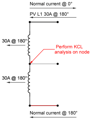
No wrong assumptions on my part. PV L2 is zero amperes and degrees to the utility. What you marked in red is via POCO transformer... but it is same current that originated from PV L1. It then goes through the load then back to PV L1 via the neutral. There is no additive neutral current.
 
Status
Not open for further replies.
Top