JonathanWaldner
Member
- Location
- Cut Bank
- Occupation
- Electrician
Just wondering what size wire do i need if my run is 4000 feet at 480 from my switch wanting to step it up to 7200 an then from 7200 down again to 208/120 what size wire will i need
It will be a 400 amp serviceJust wondering what size wire do i need if my run is 4000 feet at 480 from my switch wanting to step it up to 7200 an then from 7200 down again to 208/120 what size wire will i need
That is at 208/120Welcome to the forum.
You left out the most important info: calculated load current (and intended capacity).
Yes it is underground That is what I dont know which wire I should useWhat type of wire do you plan on using for the 7200? Is it underground or overhead?
Yes from 480 up to 7200 and on my other end down to 208/120 I might never pull 400 amps but this is for futureSo you're going from 480 step up to 7200 and then back down to 208Y/120, 400 amps at the end with a total length of run 4000'?
Direct burial and in a poly type conduitIt's not as simple as just sizing. You will need to use a 15KV type cable. Is it going to be in conduit or direct burial? Have you ever made MV terminations? It might be worth consulting with a local EE or EC that has done this type of work.
You did not say if this was a single phase or 3 phase serviceJust wondering what size wire do i need if my run is 4000 feet at 480 from my switch wanting to step it up to 7200 an then from 7200 down again to 208/120 what size wire will i need
It is a 3 phase runYou did not say if this was a single phase or 3 phase service
Assuming this is a 3 phase service I calculated as small as a # 10 AWG conductor for the 4,000 foot feeder span between the two transforners (ONLY THIS 4000 ft section run)
It may seem too small but with such as high 7,200 volts your output current will be so low 11.554 I amperes estimated
144 Vd = 1.732 x 12.9 (copper) x 11.555i (amperes) x 4,000 (one way distance) / wire circular mill
Solve for CM = 7,171.42
#10 AWG = 10,380 cm circular mills size
The maxim voltage drop on the 4,000 foot run will be 144 volts to be within a 2% max voltage drop for the feeder/ link between transformers
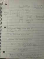
For a 3 phase system you may need 144.1 kVA transformers minimum. See picture working from second transformer up its:
400 I amperes output secondary to service disconnect at 208/120 E
Second transformer primary
primary 11.555 i ampere at 7,200 E volts
First transformer feeds second transformer primary at 7,200 E at 11.555 i amperes
First transformer primary sees 173.25 i amperes at 480 volts
What i do not know is why calculating voltage drop using chapter 9 table 8 wire resistance yields a different VD value other than 144 volts dropped?
First voltage drop method = 144 volts
1.732 (3 phase) x 12.9 (copper) x 4,000’ (feet) / circular mill = 144 VD
Second voltage drop method
I X R
11.555i x 1.21 (ohms per 1,000 ft) x 4000’ x 2 (two way distance) / 1,000 = 111.85 i VD
Clearly both methods are acceptable for calculating voltage drop but why do they always yield inconsistent results? 144 Vd does not equal 111.85 VD?
Don't you need a special wire if you go over 600 volts I usually used 4/0 but that is only rated for 600 volts so what kind of wire would you use for thatIt is a 3 phase run
Did you read post #11Don't you need a special wire if you go over 600 volts I usually used 4/0 but that is only rated for 600 volts so what kind of wire would you use for that