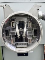
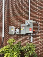
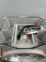
In this setup with the solar panels I see the EGC coming out of the 3/4” EMT. If there’s a ground fault for example inside the conduit does the fault current want to travel back to the transformer neutral or back to the solar panels?
My understanding is if there is a line to ground fault in the AC output circuit of a grid tied inverter, say at the inverter housing, any current output by the inverter will flow back to inverter the shortest path it can take. So if the inverter can output a max of 56 amps and the fault happens in full sun when its putting that out, 56 amps will flow back to the inverter the shortest path it can take.
I suspect modern inverters will detect this condition rather quickly and disconnect themselves.
And likewise all the available current from the utility transformer will try to take the shortest path back to the transformer. In essence fault current flows on all possible paths back to its source.
As for the DC side if the inverter is putting out 56 amps @ 240VAC then you could have a DC side of say 20Amps @ 700 VDC or some similar high voltage/low current depending how the solar panels are stringed together, and I imagine the wire sizes on the DC side can carry a bolted DC fault continuously.
During a catastrophic bolted inverter AC side fault (say internal to the inverter) I don't think the DC side would see anything other than a large load.
I still think of the DC side of an inverter as a 'one way gate valve' isolated from the AC side, (there is no isolation transformer in a grid tied inverter) but I am no expert on inverter design. I imagine the isolation provided by the electronics of an inverter is equivalent to that of a transformer and what we think of as a 'Separately Derived System' though they are not considered that code wise.
I have never herd of a grid tied inverter failure mode where say fault current from the grid flows thru the inverter or high voltage DC flows out on the AC side, but obviously faults happen during accidents, storms and unforeseen events so anything is possible.