Testing grounding electrode system

Isaiah

Senior Member
Location
Baton Rouge
Occupation
Electrical Inspector
Is there a way to test the grounding electrode system for a building if there is no ground test well available?


Sent from my iPhone using Tapatalk
 

winnie

Senior Member
Location
Springfield, MA, USA
Occupation
Electric motor research
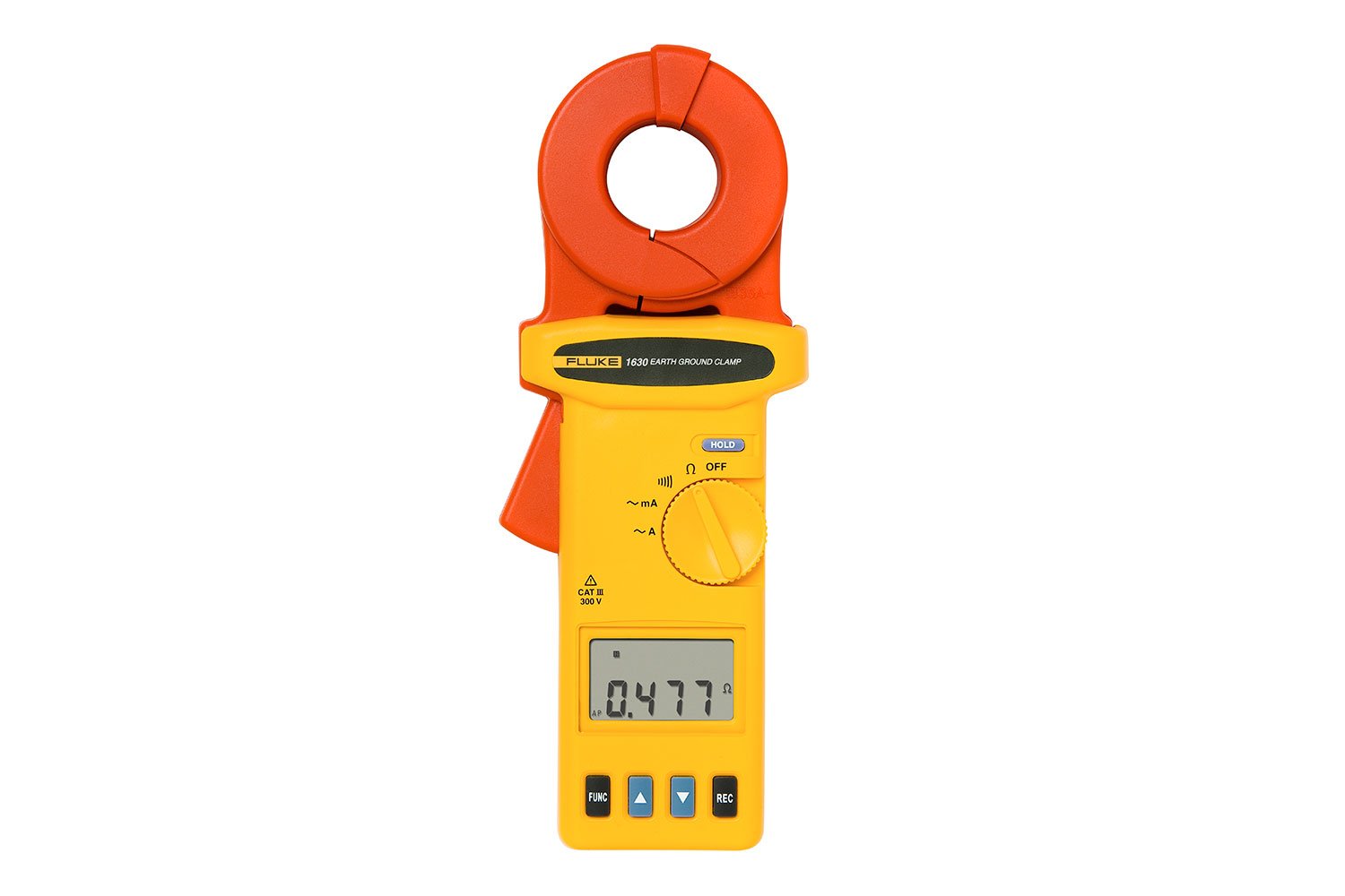
The clamp on ground resistance meters _cannot_ measure the resistance of a single grounding electrode. What they can do is measure the resistance of a circuit which includes at least two grounding electrodes.

If the GEC is the single isolated connection from the grounding electrode that you want to test back to your system neutral, then the clamp on resistance meter will measure the resistance of the grounding electrode in series with the vastly lower grounding resistance of the utility supply, which will be a good approximate measurement of the building grounding electrode system.

Similarly, if you have access to a single conductor going to a single electrode, then you can get the resistance of that single electrode in series with the lower resistance of the rest of the system, and get a good measurement of that single electrode.

But if you have a loop in your GEC and put the clamp around it (say GEC to building steel and there is another bonding connection to building steel), then you might just end up measuring the resistance of that metallic loop, not any of the electrodes. Or you might end up measuring multiple electrodes in parallel.

-Jon
 

W@ttson

Senior Member
Location
USA
The clamp on ground resistance meters _cannot_ measure the resistance of a single grounding electrode. What they can do is measure the resistance of a circuit which includes at least two grounding electrodes.

If the GEC is the single isolated connection from the grounding electrode that you want to test back to your system neutral, then the clamp on resistance meter will measure the resistance of the grounding electrode in series with the vastly lower grounding resistance of the utility supply, which will be a good approximate measurement of the building grounding electrode system.

Similarly, if you have access to a single conductor going to a single electrode, then you can get the resistance of that single electrode in series with the lower resistance of the rest of the system, and get a good measurement of that single electrode.

But if you have a loop in your GEC and put the clamp around it (say GEC to building steel and there is another bonding connection to building steel), then you might just end up measuring the resistance of that metallic loop, not any of the electrodes. Or you might end up measuring multiple electrodes in parallel.

-Jon
This is very important. People rent or buy those clamp on ground resistance meters and end up not setting up the circuit correctly and get erroneous results. This post gives good info on setting it up correctly.
 

jim dungar

Moderator
Staff member
Location
Wisconsin
Occupation
PE (Retired) - Power Systems
I agree. I see no point in testing the grounding electrical system for a typical building. It really doesn't do much of anything in terms of the operation or safety of the system.
I would use a clamp-on style ground tester to see if metallic paths were actually bonded together. The exact measurement was not of concern but there shouldn't be much variance either.

I have done this to verify the visible copper conductors, cadwelded to building steel, were also still connected to the 80 year old buried ground grid. In another case I looked at the conduit mounted on a removable conveyor versus conduits on fixed in place equipment and discovered significantly different readings indicating a poor bonding condition.
 
Last edited:
Top