Transformer Bonding/Grounding Help

JARV1S

Member
Location
USA
Occupation
Electrician
Hey everyone! Transformers are not generally something I work on and I need some help with grounding/bonding that I cant seem to wrap my head around... There's a lot of conflicting/confusing information surrounding these out there on different forums and some diagrams completely confict with eachother.

This is for a customer who has service at the front of his property for a farm building but the new house sits back almost 1600' from that service panel. POCO wanted 30k+ to run the line and charges a $50/mo per meter fee so he didn't want the double monthly fee and instead opted to go the xfmr route. Step up/step down is on site (nameplate pictures attached) but I want to get this in my head straight before I put any current through them.

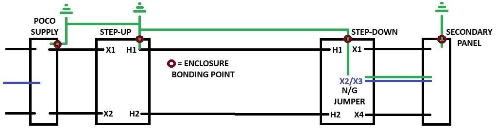
Is my crude paint diagram below correct? I don't need anyone getting hit by 600v so really want to make sure this is 100%. I have also seen some people reference that the enclosure bonding needs to be separate from the ground - couldnt current just travel through the enclosure anyway whether separate/together since they are all bonded together and the enclosures are bonded to ground on both the service panel and secondary sides? If it needs to be separate, I assume that the pre-installed ground lugs are for bonding specifically? Like I said, just really don't want someone (or myself) to get hurt once these are energized so want to make sure this gets done right.
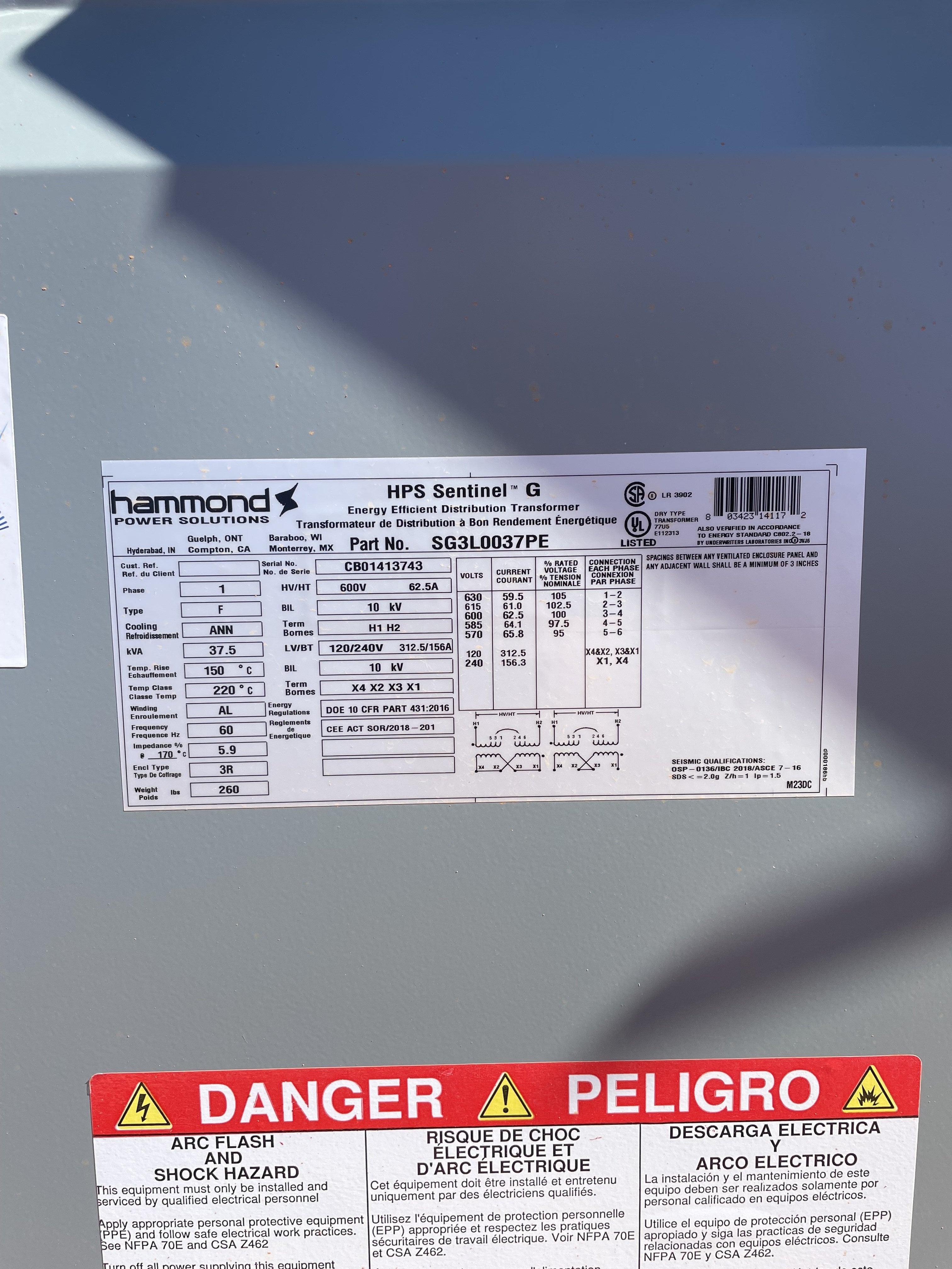
step-up-and-step-down-diagram-jpg.186915
img_0995-jpg.186914
img_0994-jpg.186913
 

ruxton.stanislaw

Senior Member
Location
Arkansas
Occupation
Laboratory Engineer
Is it possible that the power company can supply the customer with 600 or 480 V service? That would save the losses of the first transformer.
 

JARV1S

Member
Location
USA
Occupation
Electrician
Is it possible that the power company can supply the customer with 600 or 480 V service? That would save the losses of the first transformer.
No they asked, and he also asked if they would do a reduced rate on the second meter fee for the same property... No dice. It's 240 only unless he wants commercial rates which he doesnt... Xfmr losses should still be under the $50/mo extra fee so I think that's where he believes he's ahead in the long run. He may also build an additional farm building on a different part of the property later down the road and would then get tagged with a 3rd fee... (this is a rather large farm)

Either way he already bought these xfmrs and they are on site ready to install with lines pulled. I just want to nail down the bonding/grounding before I hook them up for him.
What you want to do is use 250.30(A) (1) exception #2. This allows for just 2 conductors - one of the conductors is a grounded conductor and doubles as the EGC. If the conductors are already installed, you can do 3 wire as you have in the diagram.

Do you have you 450.3(B) and 240.21(C) protections?
 

JARV1S

Member
Location
USA
Occupation
Electrician
What you want to do is use 250.30(A) (1) exception #2. This allows for just 2 conductors - one of the conductors is a grounded conductor and doubles as the EGC. If the conductors are already installed, you can do 3 wire as you have in the diagram.

Do you have you 450.3(B) and 240.21(C) protections?
Yeah the triplex wire is already pulled so will be going with the 3rd wire and connecting it to H1, the enclosure, and the ground rod at the step-up xfmr.

Yeah I have a 200 amp load center with main breaker located within 10' on the secondary side. 100 amp 600v fused disconnect on the primary side between the xfmrs - hopefully enough room to handle any potential inrush.

One last follow-up question for you - someone I talked to earlier mentioned I should add a ground rod on the step-down xfmr. Would this have any actual benefit/reason to add one?

Appreciate everyone's feedback, this forum has been extremely helpful on multiple occasions although I usually lurk in the shadows as most of my questions have already been asked by someone else.
You need a grounding electrode for the secondary of the step down. It goes the same place as you put the SBJ. Mike has a good graphic, I can't find it maybe someone can post .

Inrush will likely be a problem for the step up. I am having problems with a 25kva on a 125. Guess you can just see how it goes, might take a few tries to start it.
 

jim dungar

Moderator
Staff member
Location
Wisconsin
Occupation
PE (Retired) - Power Systems
If you are running your step-up transformer in reverse:

You can expect the inrush current to be much higher than normal. As mentioned by electrofelon, I would use the largest primary side protection possible.

The taps will work differently than normal, but you might want to adjust them to provide the highest output voltage possible.
 
I have also seen some people reference that the enclosure bonding needs to be separate from the ground - couldnt current just travel through the enclosure anyway whether separate/together since they are all bonded together and the enclosures are bonded to ground on both the service panel and secondary sides? If it needs to be separate, I assume that the pre-installed ground lugs are for bonding specifically?
Think of a transformer as being like any other device for equipment grounding. Your incoming EGC, outgoing EGC (called a supply side bonding jumper but whatevs), and the transformer case all get connected together (forget about that special exception I mentioned allowing the grounded conductor to serve as the EGC). Now if you are making a grounded conductor as we almost always do, then that conductor needs to bond to the EGC system somewhere, but at ONE POINT. You can do that at the transformer or at the first disconnect. Wherever that bond is made, you also land your GEC.
 

JARV1S

Member
Location
USA
Occupation
Electrician
You need a grounding electrode for the secondary of the step down. It goes the same place as you put the SBJ. Mike has a good graphic, I can't find it maybe someone can post .

Inrush will likely be a problem for the step up. I am having problems with a 25kva on a 125. Guess you can just see how it goes, might take a few tries to start it.
That makes sense - I was hoping as it's a dedicated step up xfmr, not a reverse fed step down, that it would help reduce the inrush. Do you think a 600V 200A disco would give enough room?

If you are running your step-up transformer in reverse:

You can expect the inrush current to be much higher than normal. As mentioned by electrofelon, I would use the largest primary side protection possible.

The taps will work differently than normal, but you might want to adjust them to provide the highest output voltage possible.
Step up is a dedicated step up xfmr per the name plate, I know we can go up to 250% on the primary, but was hoping because it's specifically built to step up that would reduce the inrush.

Think of a transformer as being like any other device for equipment grounding. Your incoming EGC, outgoing EGC (called a supply side bonding jumper but whatevs), and the transformer case all get connected together (forget about that special exception I mentioned allowing the grounded conductor to serve as the EGC). Now if you are making a grounded conductor as we almost always do, then that conductor needs to bond to the EGC system somewhere, but at ONE POINT. You can do that at the transformer or at the first disconnect. Wherever that bond is made, you also land your GEC.
Yes that makes sense - I believe this is the setup you were originally referring to with SSBJ exception, so I am basically doing the same except running a separate EGC between the xfmrs instead of utilizing the primary conductor as the SSBJ. XFMR STEP UP STEP DOWN DIAGRAM.jpg
 

jim dungar

Moderator
Staff member
Location
Wisconsin
Occupation
PE (Retired) - Power Systems
Sorry, I didn't zoom in on the label.

Did you ask the step-up transformer manufacturer for their expected inrush value?
Are you feeding it with fuses or a breaker?

You should still adjust your taps to give you the highest possible output voltage.
 

JARV1S

Member
Location
USA
Occupation
Electrician
Sorry, I didn't zoom in on the label.

Did you ask the step-up transformer manufacturer for their expected inrush value?
Are you feeding it with fuses or a breaker?

You should still adjust your taps to give you the highest possible output voltage.
No issues at all! Didnt mean it as a call out on you in any way, just informing so you guys have all the context for the setup. You guys have all been amazing and are an incredible source of knowledge so I'll gladly take any input given and at least clarify or ask questions so I can learn more from you all.

I did but upon second look (I must not have had my coffee that morning) at the email they sent, they stated they generally recommend 200A not 100A.

Step up trans is being fed off a 200A CB in the service panel.

I want to make sure I'm following you on your last statement - what benefit does the highest output voltage provide on the primary other than VD?
 

JARV1S

Member
Location
USA
Occupation
Electrician
Just that higher voltage means less voltage drop issues, so take advantage of it if you can.
Ah perfect, so we are on the same page. Didnt know if you were saying there was some other benefit as well.

Great so I think we've sorted the setup, it should be safe to go ahead with my initial diagram from the first post? (Obviously with disconnects/OCPD that I didnt add in the diagram)


Appreciate all of you!
 
We had a recent thread on transformer inrush and OCPD size needed. There doesn't seem to be any quick and dirty way to tell if it's going to be an issue without looking at the transformer inrush current (if you can get it from the manufacturer) and the trip curves of the OCPD. It's not that it won't work, sometimes it will trip sometimes it won't. The one I was talking about in the other thread was 104A FLC on a 125 breaker and it trips about 1 out of 3 to 4 times. You could just tell the client that might happen and thus he may have to go reset it after a power outage. He may just prefer that over the cost of a 400A disconnect.
 
Top