UK wiring style

Status
Not open for further replies.

ronaldrc

Senior Member
Location
Tennessee
The way I see it is we are just changing the circuit.If we couldn't do that
we wouldn't be Electricians.

Wiring methods would be making sure you used White or Gray as a neutral
or grounded conductor, Bare,green for grounding conductor
and Black, red and blue Etc for hots.

Rather its a parallel circuit or not is undecided.

Just my assumption and everyone has one.

Ronald :)
 

PetrosA

Senior Member
The NEC is also silent about whether the ground prong should be up or down. So does that mean they can be neither, and all of your outlets have to be mounted sideways? :lol:


110.8 is about the most bogus statement in the whole NEC. "Recognized" by whom? It doesn't even state who, how, or where a method is recognized and how it is determined whether or not something is recognized or not.

So for instance, if I wanted to install 12v lamps in recessed fixtures in someone's house, I could wire ten of them in series on a 120V line and that would be ok? As long as I use proper size NM, I could just wire the blacks to the lamps and connect the neutrals together and connect at the last fixture, right?

Ground up or down or sideways isn't a wiring method. Topology of a circuit is, which makes ring circuits a wiring method not discussed in the code. It doesn't matter who recognizes it - if it's not discussed in the NEC, it's not recognized by the NEC and therefore in violation of the NEC.

The problem here is that the OP describes a situation where someone from UK installed a ring circuit. Their way of doing it would very likely violate a bunch of things in the NEC since it's considered ok to run a 30A circuit on a wire rated for lower amps and divide the loads to either side of the ring, thereby (theoretically...) not overloading the wire. They also have fused plugs, which I'm certain weren't part of the ring he designed here. My point being that they do have a developed set of guidelines for designing and using ring circuits which we don't have and which could make the ring design dangerous to use here.
 

iceworm

Curmudgeon still using printed IEEE Color Books
Location
North of the 65 parallel
Occupation
EE (Field - as little design as possible)
Typical primary loops go through switches in the transformers. Any transformer or loop section can be de-energized using the switches in the adjacent transformers.

It is a parallel wiring method, but not considered parallel conductors because of the switching.

That doesn't make any sense at all. I think the NEC doesn't consider this design at all - ignores that it might even exist

So, who (specifically) is deciding this design is a parallel wiring method but is not considering the conductors are paralleled. :?:?:?

JAO: At 120V everybody is in the discussion - everybody has an opinion. At 13.8kv, nobody is in the discussion - designs are just accepted as drawn. That's the difference

ice
 

iceworm

Curmudgeon still using printed IEEE Color Books
Location
North of the 65 parallel
Occupation
EE (Field - as little design as possible)
So for instance, if I wanted to install 12v lamps in recessed fixtures in someone's house, I could wire ten of them in series on a 120V line and that would be ok? As long as I use proper size NM, I could just wire the blacks to the lamps and connect the neutrals together and connect at the last fixture, right? ....

I would wonder, "Why?". But since I am not the engineer of record, me wondering is a, "So what.?". You would have to use 120V rated fixtures - but I think you can get 12V bulbs that will fit the 120 fixtures. Other than the inspector saying, "I haven't seen that before - REJECTED.", there likely isn't anything unsafe about it. Yes, I am certain one could cite any of a half-dozen god-clauses in the NEC as the reason for rejection.

BTW: That is the way airport runway and taxiway lighting is put in. They are all series - and they don't even run the hot and return together. It is just one BIG loop. Why? Cause it is a lot cheaper for the copper and the voltage drop problems disappear.

ice
 
Last edited:

Rick Christopherson

Senior Member
So for instance, if I wanted to install 12v lamps in recessed fixtures in someone's house, I could wire ten of them in series on a 120V line and that would be ok? As long as I use proper size NM, I could just wire the blacks to the lamps and connect the neutrals together and connect at the last fixture, right?
Hmmm, where have I seen that before? Oh, you mean like Christmas tree lights, where one bulb goes out, they all go out? :lol:
 

Smart $

Esteemed Member
Location
Ohio
That doesn't make any sense at all. I think the NEC doesn't consider this design at all - ignores that it might even exist

So, who (specifically) is deciding this design is a parallel wiring method but is not considering the conductors are paralleled. :?:?:?

JAO: At 120V everybody is in the discussion - everybody has an opinion. At 13.8kv, nobody is in the discussion - designs are just accepted as drawn. That's the difference

ice
If I have to name names, that would be me, at this particular point in time. I have not been involved with a 13.8kV primary loop for probably ten years... and I'm lucky if I can remember the names of people I've worked with just this year let alone ten years ago.

Additionally, switch out one section of the loop and all meets NEC requirements. It has never been up to me to verify that one section is switched out.
 
Hmmm, where have I seen that before? Oh, you mean like Christmas tree lights, where one bulb goes out, they all go out? :lol:

Kinda of that idea but read Iceworm's comment carefull espcally with higher voltage level.

I would wonder, "Why?". But since I am not the engineer of record, me wondering is a, "So what.?". You would have to use 120V rated fixtures - but I think you can get 12V bulbs that will fit the 120 fixtures. Other than the inspector saying, "I haven't seen that before - REJECTED.", there likely isn't anything unsafe about it. Yes, I am certain one could cite any of a half-dozen god-clauses in the NEC as the reason for rejection.

BTW: That is the way airport runway and taxiway lighting is put in. They are all series - and they don't even run the hot and return together. It is just one BIG loop. Why? Cause it is a lot cheaper for the copper and the voltage drop problems disappear.

ice

Ya I know the Areoport runway and taxiway luminiare are wired in series and the typical voltage they used over N/A ( North Americia side ) 4,160 volts ( few case 2,200 volts )

But over here it can be either 2.2 or 4.4 KV depending on the layout and one major qurik it will remind you very clear is make sure you shunt them when you work on any series luminaire or remove the power source ( this is the best methold once you know which luminare is out ) and almost all the series luminaire will have constant current transfomer so that is the major item you will have to watch out if not.,,

They can build up pretty high voltage and can scare the stink out of ya and it useally not a faint of heart to troubeshooting this.

Merci,
Marc
 

kwired

Electron manager
Location
NE Nebraska
I did not read all posts, so forgive me if I stole someones thunder.

A ring circuit has conductors in parallel, but does not have parallel conductors, unless there is only one outlet.

If you run a ring circuit with 12 AWG and provide 20 amp overcurrent device - you will never have any overloaded segment in the circuit. If you run a ring circuit with 12 AWG and provide 40 amp overcurrent protection, how can you possibly guarantee you will never have more than 20 amps on any segment of the circuit? Forget the minimum parallel conductor size of 1/0 for a moment, if you followed all other rules for "parallel conductors" and placed two 12 AWG in parallel with 40 amp protection, you should only have 1/2 of the total current drawn being on each 12 AWG and they are protected by the 40 amp device. The key is keeping all characteristics of the two conductors the same so they each have same impedance.

The fact that all circuit conductors are not in same raceway or cable does complicate this some. The biggest issue with that is not that there isn't a hot and a neutral in both sides of the ring, but how do you ensure that, from the source, hot conductor "A" is carrying equal amount of current as neutral conductor "A". If they are not the same then the "B" source conductors are not going to be the same either.

I think the reason most would use this circuit would be because
of voltage drop.I do not know of any NEC. section that would not allow it.
Each feeder contains a returning conductor to cancels any eddy currents.


Ring circuit feeder.jpg


Ronald :)
As I said above, how do you ensure that current in each conductor of the top cable is the same as the current in each conductor in the bottom cable? That is I think, the biggest problem with this kind of a circuit. If top cable has 10 amps on the hot and 5 amps on the neutral you will have EMF's, eddy currents and inductive heating.

But the only reasoning to run a ckt in parallel is to increase its ampacity. If not increasing ampacity it should not, for any intent or purpose be considered a parallel circuit.
Only reason to increase an individual conductors size may only be because of voltage drop. If you increase a 12 AWG to 10 AWG for voltage drop reasons, you still put it on a 20 amp overcurrent device, because you still are still considering it to be a 20 amp conductor.

A significant difference between UK and US wiring is that here (and, as far as I know, most of EU land) uses single phase 230V for dwellings. The centre tap arrangement is not used. Everything operates at 230V. Wiring in dwellings is usually flat twin and earth (your ground) cable. Live, neutral, and earth. Brown, blue, and bare copper with an outer sheath which is grey - I don't know if the grey is mandatory but I've never seen any other colour used. I haven't seen metallic conduit used in decades.

True, but the circuit in discussion here doesn't really care what voltage is applied. Same argument applies to any voltage.

The only reason I would even consider a ring circuit would be for voltage drop.

For redundancy or back up it would give you a sense of false security.
One feed might be loose for years before anyone would notice and may be never.


Disadvantage or drawback.

Chances of this ever happening would be very slim.

If you where to loose your hot on one circuit and your neutral on the other
or vise versa on your feeders, you would loose your inductive canceling
effect of the circuit.

If this circuit where loaded to the gills with say a coffee maker and a
freezer this would be a very dangerous situation.

This would make the 310. rule for all the conductors of the same circuit
to be bundled together even more important in this case.


Ronald :)

Like I said before inductive canceling is probably the biggest problem with this circuit. Load it to the gills, what is so dangerous? Unless it is 12 AWG conductors connected to a 40 amp breaker. If it is on a 20 amp breaker the breaker still trips if the load exceeds 20 amps for too long, same thing happens if it is not a "ring" circuit.
 

renosteinke

Senior Member
Location
NE Arkansas
Each cable has both a 'hot' and a 'neutral.' You won't get inductive heating from any sort of 'ring' circuit.

"Parallel feeders" are a means to make a big wire out of several smaller ones. "Ring" circuits do not reduce the size of any wire. For example, if your branch circuit normally used #12, as a ring circuit it would be fed by two #12's. This is, in contrast, to using parallel 250's because you can't fit 500's in the pipes.

Thus, there is no intent, or desire, to have the load suplied equally by each side of the 'ring.'

So, why do the Brits do things this way? Just to confuse the French, I suppose :D . I mean, why else drive on the wrong side of the road?
 

Rick Christopherson

Senior Member
These two sentences were reversed by Rick C.
Like I said before inductive canceling is probably the biggest problem with this circuit.


If top cable has 10 amps on the hot and 5 amps on the neutral you will have EMF's, eddy currents and inductive heating.
First off, the issue with inductive heating is negligable at 20 amps. If it were a critical issue, then we would have significant inductive heating in the main load center where the CCCs were separated right after entry into the load center. I haven't seen any thermal pictures, but the area around the neutral bus would be the greatest concern.

In the second sentence I quoted above, you suggested that the hot conductor could have 10 amps but the neutral could have 5. Both conductors are of the same length, so they will have the same resistance. Their amperage should be the same unless there is a very poor connection somewhere in the circuit. Which is in fact one of the things a ring circuit can mitigate.
 

kwired

Electron manager
Location
NE Nebraska
First off, the issue with inductive heating is negligable at 20 amps. If it were a critical issue, then we would have significant inductive heating in the main load center where the CCCs were separated right after entry into the load center. I haven't seen any thermal pictures, but the area around the neutral bus would be the greatest concern.

In the second sentence I quoted above, you suggested that the hot conductor could have 10 amps but the neutral could have 5. Both conductors are of the same length, so they will have the same resistance. Their amperage should be the same unless there is a very poor connection somewhere in the circuit. Which is in fact one of the things a ring circuit can mitigate.

Yes they are same length, yes poor connection will change that, that is exactly what I had in mind when I wrote it.

If that happens it can run that way for years before another problem develops that actually makes a noticeable difference in performance, in the meantime you do not have same current going out in one cable or raceway that comes back.

Inductive heating may be negligable at 20 amps, but we are still supposed to run all circuit conductors together to help prevent this are we not? Last I knew you are not supposed to run a single conductor in a magnetic raceway whether it carries 5 amps or 500 amps.
 

Rick Christopherson

Senior Member
Inductive heating may be negligable at 20 amps, but we are still supposed to run all circuit conductors together to help prevent this are we not? Last I knew you are not supposed to run a single conductor in a magnetic raceway whether it carries 5 amps or 500 amps.
And they are all run in the same raceway. You're claiming a wiring failure as though it was something other than what it is.

You're grasping at straws. A loose connection could happen on a legal parllel 1/0 feed, and when it does happen, it will smoke the good conductor. But unless and until that loose connection takes place, it is still a legal install. You don't call something non-compliant on the basis of what "might happen" on a circuit failure.

Edit: Woud you call a grounded circuit non-compliant today on the basis that there is a chance that sometime in the future a wire nut could come loose and it would no longer be a grounded circuit in the future?
 
Last edited:

kwired

Electron manager
Location
NE Nebraska
And they are all run in the same raceway. You're claiming a wiring failure as though it was something other than what it is.

You're grasping at straws. A loose connection could happen on a legal parllel 1/0 feed, and when it does happen, it will smoke the good conductor. But unless and until that loose connection takes place, it is still a legal install. You don't call something non-compliant on the basis of what "might happen" on a circuit failure.

Edit: Woud you call a grounded circuit non-compliant today on the basis that there is a chance that sometime in the future a wire nut could come loose and it would no longer be a grounded circuit in the future?

Did I ever say anything was non-compliant? If I did, or came across that way it was not intentional. I have been in this very debate on this forum before, and AFAIK it was somewhat of a stalemate.

I come into this particular thread with a neutral position as to whether or not it is code compliant, and simply want to point out both advantages and disadvantages of such an install. I honestly do not know if "ring" circuits are NEC compliant. I do lean toward it not being compliant a little but not so much that I am totally convinced it is not allowed either. Keeping all circuit conductors in same raceway or cable is my strongest argument that leans toward it not being allowed.

I do not believe the ring circuit contains "parallel conductor sets" as is required by NEC when installing parallel conductors but does contain conductors that are parallel to each other.

I do not see the advantages as being significant enough that I would install a "ring" circuit either for most 120 - 600 volt circuits. For anything smaller than 1/0, the extra copper used for voltage drop on a long run may as well have been a larger single conductor from a cost perspective IMO. I do see it as an advantage for reducing voltage drop in low voltage lighting circuits, or similar installations.

Yes, there are failures on "conventional" parallel conductors that have the same types of effects.

Yes EGC conductors do sometimes fail, usually the fault of an installer. I also believe a current carrying conductor has more of a chance of failure than an EGC assuming good mechanical connections were made at installation, for the simple fact that current comes with heating effects, and an EGC is not intended to see current except in fault conditions.
 

kwired

Electron manager
Location
NE Nebraska
That's a bit irrelevant as far as UK wiring is concerned - we don't, or hardly ever, use metallic conduit.

I would guess it is still a common practice or even a code or standard to run supply with return conductor(s) so that EMF's cancel and also results in lower impedance in conductors.
 

Besoeker

Senior Member
Location
UK
I would guess it is still a common practice or even a code or standard to run supply with return conductor(s) so that EMF's cancel and also results in lower impedance in conductors.
There isn't much choice if you run flat twin and earth.
The conductors are all within one sheath.
 

Rick Christopherson

Senior Member
Keeping all circuit conductors in same raceway or cable is my strongest argument that leans toward it not being allowed.
I don't understand how you can think they are not all in the same raceway. That requirement is so that all hots, neutral, and ground are in the same raceway for a given segment of a branch. That doesn't mean that all segments of a branch circuit must be in a single raceway. That would prevent you from ever making a T-junction somewhere along the branch.

If you are making this assertion on the basis of losing one conductor, then that goes back to what I previously said. You are suggesting this would be non-compliant on the basis of a "failure", not on a proper install. In the absence of a conductor failure, they are all in the same raceway.

If you predicated compliance on the basis of having a conductor failure, then the entire section on parallel conductors would have to be thrown away, because the loss of any single conductor would overload the remaining conductors.

By the way, I am not necessarily advocating or championing ring circuits. I'm just pointing out that they are not prohibited by the NEC.

As an off-topic but similar topic, I specifically set up the dust collection system in my workshop as a ring circuit. This too is generally "poo-poo'd" by conventional wisdom, but I deliberately did it to ensure that the farthest tool from the dust collector (which is also the highest demand) always had maximum air flow regardless of any restrictions in the system.
 

kwired

Electron manager
Location
NE Nebraska
I don't understand how you can think they are not all in the same raceway. That requirement is so that all hots, neutral, and ground are in the same raceway for a given segment of a branch. That doesn't mean that all segments of a branch circuit must be in a single raceway. That would prevent you from ever making a T-junction somewhere along the branch.

If you are making this assertion on the basis of losing one conductor, then that goes back to what I previously said. You are suggesting this would be non-compliant on the basis of a "failure", not on a proper install. In the absence of a conductor failure, they are all in the same raceway.

If you predicated compliance on the basis of having a conductor failure, then the entire section on parallel conductors would have to be thrown away, because the loss of any single conductor would overload the remaining conductors.

By the way, I am not necessarily advocating or championing ring circuits. I'm just pointing out that they are not prohibited by the NEC.

As an off-topic but similar topic, I specifically set up the dust collection system in my workshop as a ring circuit. This too is generally "poo-poo'd" by conventional wisdom, but I deliberately did it to ensure that the farthest tool from the dust collector (which is also the highest demand) always had maximum air flow regardless of any restrictions in the system.

OK, with the ring circuit or conventional paralleled conductors if you have a connection failure in either yes they both still continue to operate and users never know there was a failure. With the ring circuit you end up with uneven current on the supply and return conductors so EMF's don't cancel, and other things associated with that come up. As long as the conductor is sized according to overcurrent device there is no overloaded conductors though. With the "conventional parallel conductor" one of the conductors of the "set" ends up carrying more or even all the current, and may become overloaded.

I don't have the opinion that either is superior, unacceptable, or otherwise, I also believe that every install has its own merits as to what is best and what is worth compromising.
 

Smart $

Esteemed Member
Location
Ohio
Did I ever say anything was non-compliant? If I did, or came across that way it was not intentional. I have been in this very debate on this forum before, and AFAIK it was somewhat of a stalemate.

....

I do not believe the ring circuit contains "parallel conductor sets" as is required by NEC when installing parallel conductors but does contain conductors that are parallel to each other.

....
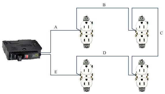
Let's settle this :huh:

Parallel.gif


Only the ungrounded conductor is shown for simplicity.

The only thing close to a definition of parallel conductors in the NEC is AFAIK in 310.10(H)(1)... "electrically joined at both ends".

Pick any two wires A thru E. Are they electrically joined at both ends?

Additionally, let's say each wire is contained in a separate raceway or piece of cable. If a load is connected to any one receptacle, is there circuit current on each piece of wire? (Yes) So if you have circuit current flowing in say B and D, how does this meet Code for all conductors of the same circuit to be in the same raceway or cable?
 
Status
Not open for further replies.
Top