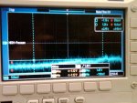
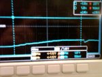
I have several pictures I am trying to attach, but some not letting me upload. The first attachment is what the scope shows while the drive is running. The second picture is what the scope normally shows.
You are using an out of date browser. It may not display this or other websites correctly.
You should upgrade or use an alternative browser.
You should upgrade or use an alternative browser.
VFD Question What is this doing???
- Thread starter C3PO
- Start date
- Status
- Not open for further replies.
gar
Senior Member
- Location
- Ann Arbor, Michigan
- Occupation
- EE
110531-0816 EDT
C3PO:
If the drive system with the installed filter is doing what it is expected to do, you have indicated that it is, then don't worry about the filter. The time constant is 20,000 * 1 / 1,000,000 = 20 milliseconds. The 3 db roll-off point is 8 Hz. A useful calculator for this is the Shure Brothers Reactance Slide Rule if you can find one. A single RC filter has a 3 db point where Xc = R.
Since you get the hash noise on the scope when the drive is on and not when it is off, then try to isolate how it gets into the scope.
First, I would power the scope and Validyne electronics from a battery source and no explicit connection to an EGC or earth. This might mean a car battery and an inverter, or some other means.
If this solves the problem, then connect the scope common to the EGC, but still powering everything from the battery. If noise is present at this point, there are a number of branching directions to see how the noise enters.
If no noise, then connect only the scope to AC power and only ground thru the scope EGC wire.
Enough for now.
.
Here are a few things you could check:
The transducer wiring should be ran in a shielded cable. I believe the shield should be connected on one end only: probably at the VFD input. (Check the transducer's data sheet).
How long is the VFD output cable? If its very long, you might need an input or output reactor. Is it ran in conduit, or a shielded cable? The VFD's instructions should give you specifics on all this.
I think 4-20ma is much more noise resistant. If they had so much problems with noise, I'd think they would just use a sensor that has a 4-20 mA output.
One other thought: Bad PID tuning can make noise problems much worse. Especialy too much "D". I'm no PID expert, but my understanding is that its very common to leave off the "D" and just use a PI feedback system. Maybe someone who does more controls can verify that, or provide more insight.
- Status
- Not open for further replies.