Voltage Drop for street lights

Status
Not open for further replies.

sceepe

Senior Member
Anybody got a good Vdrop calculator for a string of light poles. I have used a simple calculator I made. However, it assumes the load is at the end of the wire. e.g. 1200' long circuit, with 400w load every 100' I need a good way to figure out what size wire I need. Assuming 4800 watts at the end of 1200' wire is a bit of overkill.
 

sceepe

Senior Member
thats similar to what everyone has. Load is assumed to be at end of the line. What I am looking for is load dispersed along the length of the circuit
 

boater bill

Senior Member
Location
Cape Coral, Fl.
Would you be able to calculate the drop per section between poles?
Start at the closest pole and work your way to the last pole.
That would take into account the load at each section of conductor and possibly save some wire sizes towards the end of the run.
 

dbuckley

Senior Member
This is an interesting exercise in optimisation, or cost reduction.

The obvious thing to do is to allocate the permissible voltage drop linearly along the 1200 foot run, calculate the power load at each lamp, and size conductors accordingly. But you might get better economic performance by splitting the voltage drop non-linearly, so that you undersize the heaviest loaded segments, and oversize the lighter loaded end, so most of the voltage drop is in the first half, or third, or some other fraction. All still fully legit.

This is a job for Excel.

Of course, the right answer is a series connected 6.6A loop :)
 

Bob NH

Senior Member
sceepe said:
Anybody got a good Vdrop calculator for a string of light poles. I have used a simple calculator I made. However, it assumes the load is at the end of the wire. e.g. 1200' long circuit, with 400w load every 100' I need a good way to figure out what size wire I need. Assuming 4800 watts at the end of 1200' wire is a bit of overkill.

EXAMPLE: (Done in Excel)
Assume 240 Volts, 3% drop is 7.2 Volts. That is 0.6 Volt per pole.

From last to first, Amps = 1.67, 3.33, 5, 6.67, 8.33, 10, 11.67, 13.33, 15, 16.67, 18.33, 20.

Resistance for 200 ft of round trip wire from last to first = 0.6 Volt/Amps so it's Ohms = 0.6 Volt/Amps, and multiply by 5 to get Ohms/kft from Table 9.

Amps Ohms Ohms/kft AWG Ohm/kFt VD
1.667, 0.360, 1.800, 10, 1.2, 0.400
3.333, 0.180, 0.900, 8, 0.78, 0.520
5.000, 0.120, 0.600, 6, 0.49, 0.490
6.667, 0.090, 0.450, 4, 0.31, 0.413
8.333, 0.072, 0.360, 4, 0.31, 0.517
10.000, 0.060, 0.300, 3, 0.25, 0.500
11.667, 0.051, 0.257, 3, 0.25, 0.583
13.333, 0.045, 0.225, 2, 0.19, 0.507
15.000, 0.040, 0.200, 2, 0.19, 0.570
16.667, 0.036, 0.180, 1, 0.15, 0.500
18.333, 0.033, 0.164, 1, 0.15, 0.550
20.000, 0.030, 0.150, 1/0, 0.12, 0.480

Total Voltage Drop = 6.03 Volts

First, I decided to use 240 volt lamps, and 3% voltage drop = 7.2 Volts
Then I allocated 0.6 Volts per 100 ft pole spacing x 12 = 7.2 Volts.
The first column is the Amps in the 100 ft run between poles from farthest set to first set at 400/240 = 1.667 amps per pole load.
The seocnd column is the resistance in that run of wire (100 ft each way = 200 ft) to produce Amps x Ohms = 0.6 Volts of drop.
The third column is the "Ohms to neutral" in 1000 ft of wire = 5X the Ohms in 200 ft.
The 4th column is the wire size that has that "Ohms to neutral" or less in 1000 ft from Table 9.
The 5th column is the actual value of "Ohms to neutral" for the selected wire size.
The 6th column is the Amps in first column x Resistance per 1000 in 2nd column divided by 5 = Voltage drop in double 100 ft run.

Total Voltage Drop is the sum of the 6th column.
 
Last edited:

RUWired

Senior Member
Location
Pa.
Bob, Are you sure about those numbers?They look pretty high at the start.
Using (2kli/vd=cm) i get
(100'-20amps-#10awg-4.97vd)(200'-18.3amps-#8awg-5.7vd)(300'-16.6amps-#6awg-4.98vd)....# 8 at the 1100' mark and # 10awg at the 1200' mark.Also using the online calculator i get a little less vd using 30 c.
Rick
 

ramsy

Roger Ruhle dba NoFixNoPay
Location
LA basin, CA
Occupation
Service Electrician 2020 NEC
Electrical Design Reference also has a nice shareware VD calculator that does the segmented calcs you want.

I divided this 1200 foot run into three segments on 480vac, and got this V-drop:

EOL 400 ft. #14cu @ 1600 VA = 7.11 Volts
Next 400 ft. #12cu @ 3200 VA = 9.28 Volts
First 400 ft. #10cu @ 4800 VA = 8.40 Volts
----------------- Tot = 25 Volts or 5.2% V-Drop
 

Bob NH

Senior Member
RUWired said:
Bob, Are you sure about those numbers?They look pretty high at the start.
Using (2kli/vd=cm) i get
(100'-20amps-#10awg-4.97vd)(200'-18.3amps-#8awg-5.7vd)(300'-16.6amps-#6awg-4.98vd)....# 8 at the 1100' mark and # 10awg at the 1200' mark.Also using the online calculator i get a little less vd using 30 c.
Rick
I added lines in my original post describing what I did. I didn't change the numbers but I added explanation.

Note that the columns start from the farthest at the top. The first run is at the bottom where 20 Amps is going through 1/0 copper. The last run with only 1.667 amps is at the top and is going through 10 AWG copper.

Each 100 ft run (2 wires) is sized to give a 0.6 Volts or less drop, for a total not exceeding 7.2 Volts.
 

Bob NH

Senior Member
Conductor Selection for Voltage Drop with Incrementally Distributed Load

Conductor Selection for Voltage Drop with Incrementally Distributed Load

Being ever the engineer, I decided to see if there is a generalized optimizing process for selecting the conductors for the incrementally distributed load problem. I used the example of the original post and tried an algorithm where the area of the conductor is proportional to the current (amps) raised to some power. I used Excel to do the calculations and found that the optimum value of the exponent is 0.5.

But there is an easier and equally efficient method for sizing the wires for the incrementally distributed load case such as the "light post" example.

1. Pick the size of conductor that would produce the required voltage drop, using the calculated current in each segment of the run. That would be #3 copper in this case.

2. Find the break point where the size can be reduced for the rest of the run to produce the required voltage drop. In this case, using #3 for the 8 sections with the highest current and #6 for the last 4 sections produced a voltage drop of 7.2 Volts and just about the theoretical minimum amount of copper. That break point depends a lot on how close the selected conductor is to the calculated minimum size necessary to achieve the voltage drop.

Three conclusions from this study:

1. It is EXTREMELY IMPORTANT to use the calculated current in each segment of the run.

2. When using the calculated current in each increment, there is something to be gained (about 15% saving in conductor metal for this case) by using more than one size of conductor.

3. There is virtually nothing to be gained by using more than two sizes of conductors in the example problem.
 

ramsy

Roger Ruhle dba NoFixNoPay
Location
LA basin, CA
Occupation
Service Electrician 2020 NEC
Bob NH said:
Three conclusions from this study:

1. It is EXTREMELY IMPORTANT to use the calculated current in each segment of the run.
2. When using the calculated current in each increment, there is something to be gained (about 15% saving in conductor metal for this case) by using more than one size of conductor.
3. There is virtually nothing to be gained by using more than two sizes of conductors in the example problem.

Does #1 include all currents that pass thru each segment, from loads originating on other segments?

Does #3 depend on #1?

Using 480, can we save more copper by using 2 conductors, rather than my 3, and keep V-drop under 25 volts?
 

Bob NH

Senior Member
ramsy said:
Does #1 include all currents that pass thru each segment, from loads originating on other segments?

Does #3 depend on #1?

Using 480, can we save more copper by using 2 conductors, rather than my 3, and keep V-drop under 25 volts?

The calculation is based on your description of 12 lights in 1200 ft at 100 ft intervals. The wiring consists of running one pair of current carrying conductors from the beginning to the end, and connecting one light between the wires of that pair every 100 ft. The first 100 ft will carry all of the current for the 12 lights. The next 100 ft will carry the current for 11 lights, etc., etc., etc., until the last 100 ft carries the current for one light.

The calculation is based on 400 watts at each post with 240 Volt lights, for a total of 12 lights and a total of 20 Amps in the first section.

Based on the wire sizes that I calculated and using 240 Volt lamps, the voltage drop is 3% or 7.2 Volts.

The 25 Volt drop for 480 Volts was by someone else and used smaller wire. You would have to find 480 volt lamp circuits.

You can save more copper with 480 Volts if you can design a system where 480 Volts will work. You would need larger wire than 12 and 14 if you are going to get to less than 25 Volts drop.

What I was trying to do was provide a process for you to do the calculation that meets your requirements, and particularly, to show how you should use the actual current in each section and how you can save metal by varying the wire size along the length of the circuit.

In the end, the design should be your design, based on your calculations, to fit the needs of the site and customer.
 

ramsy

Roger Ruhle dba NoFixNoPay
Location
LA basin, CA
Occupation
Service Electrician 2020 NEC
I should have mentioned Sceep already designed this with 480 a few days ago in his sister thread 210.6D1 and 480 parking lot lights.

While Sceep apparently got what he wanted, or isn't compelled to return to comment on his progress, I remain very interested in testing the "Three conclusions from your study:" on 480vac.

Wisdom does not define a man by his wealth, but by how well he takes his lumps.
 

sceepe

Senior Member
ramsy said:
I should have mentioned Sceep already designed this with 480 a few days ago in his sister thread 210.6D1 and 480 parking lot lights.

While Sceep apparently got what he wanted, or isn't compelled to return to comment on his progress, I remain very interested in testing the "Three conclusions from your study:" on 480vac.

Sorry for my delay in posting. I definatly got what I wanted from the post. Namely the knowledge that 1. it can be done, 2. how to do it. And 3. there is not some simple way that everone knows except for me. Thanks to all posters in this thread. A fantastic display of how to apply engineering knowledge.

As someone said, it is an interesting excercise in optimization. I am going to go with 480V, and design the system with 2-3 different graduated wire sizes. However, I have yet to decide the best way to convey this information on the contract documents.

Thanks again.
 
Last edited:

Bob NH

Senior Member
ramsy said:
I should have mentioned Sceep already designed this with 480 a few days ago in his sister thread 210.6D1 and 480 parking lot lights.

While Sceep apparently got what he wanted, or isn't compelled to return to comment on his progress, I remain very interested in testing the "Three conclusions from your study:" on 480vac.

Wisdom does not define a man by his wealth, but by how well he takes his lumps.
Send me your email address by PM if you want me to send you the Excel spreadsheet so you can check and use it.

When you use 480 Volts, the current will be less, and therefore the wire required will be smaller, so there will not be as much metal to save.

There is an interesting evaluation that is easy to make, almost by observation.

For a given power load, if you double the voltage and keep the same percentage voltage drop, then the power lost in heating the conductors is the same because power is proportional to Voltage.

But power lost is equal to (Amps squared x Ohms), and (Amps squared) is 1/4 when you double the voltage. Therefore, when voltage is doubled, resistance (Ohms) can be increased by a factor of 4 to keep the same percentage power loss and percentage voltage drop, so circular mils of wire can be reduced by a factor of 4.

Doubling the voltage can save lot of copper when large conductors are required.
 

BAHTAH

Senior Member
Location
United States
Volt Drop

Volt Drop

I use the Load-Center-Length when there are multiple loads along a feeder or branch circuit. Basically you take each load and determine its distance from the source and multiply that distance by the individual load amps. This gives you the amp/ft at each load. You then add up the total load in amps and the total amp/ft for the circuit and divide the amp/ft by the total amps. The result is the LCL. Once you have the LCL you can use that length with the total load amps to determine the conductor you will need. If I assume you are using a 240V single-phase supply and all the fixtures are 400watt, I calculated you would need a #3 Cu Min to stay within a 3% drop. I would suggest you add 15-20% for the ballast in each fixture or use the actual amps listed for the ballast and not the lamp wattage. Another suggestion would be to install a small transformer since you load is so low and boost the voltage to 480v allowing you to reduce your wire size. You may want to compare the cost of copper between 240V and 480V. You may be able to go from a #3 or #2 down to a #4 or #6.
 

Smart $

Esteemed Member
Location
Ohio
ramsy said:
Does #1 include all currents that pass thru each segment, from loads originating on other segments?

Does #3 depend on #1?

Using 480, can we save more copper by using 2 conductors, rather than my 3, and keep V-drop under 25 volts?
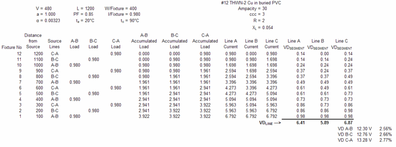
At 480V, I'd run the whole thing 3?, 3-wire, #10 THWN-2, underground PVC (or HDPE). However, if I were being conservative, my calculations say #12 would still be less than 3% VD...

VDStreetlights.gif
 

RUWired

Senior Member
Location
Pa.
Bob, In my earlier post i said that the wire sizes seemed a little high for being so close to the source.I used 3 different methods to figure vd and came up ith the same results.Method 1 was using the 2kli/vd=cm. Method 2 was using your theory,but plugging in different numbers, and method 3 was using the online calculator. The online calculator matched your theory but plugging in different numbers.See if this table looks right.

footage,amps,max vd,ohms,ohms/kft,awg,ohms/kft,multiplier,vd,calculator
1200,-- 1.66,- 7.2,-- 4.33,-- 1.8,--- 10,-- 1.2,----- 2.88,- 4.78,- 4.9.--
1100,-- 3.22,- 7.2,-- 2.16,-- .98,--- 8, -- .78,------1.71,--5.67,--5.7,--
1000,-- 4.98,- 7.2,-- 1.44,-- .72,--- 6,--- .49,------.98,---4.88,--4.9,--
900,--- 6.66,- 7.2,-- 1.08,-- .60,--- 6,--- .49,------.88,---5.86,--5.9,--
800,--- 8.33,- 7.2,--- .86,-- .54,--- 6,--- .49,------.78,---6.49,--6.5,--
700,--- 9.96,- 7.2,--- .75,-- .53,--- 6,--- .49,------.68,---6.83,--6.9,--
600,---11.62,- 7.2,---.61,-- .51,--- 6,--- .49,------.58,---6.83,--6.9,--
500,---13.33,- 7.2,---.54,-- .54,,---6,--- .49,------.49,---6.53,--6.6,--
400,---15.00,- 7.2,---.48,-- .60,---6,----.49,------.39,---5.85,--5.9,--
300,---16.66,- 7.2,---.43,-- .71,---6,----.49,------.29,---4.83,--4.9,--
200,---18.33,- 7.2,---.39,-- .97,---8,----.78,------.31,---5.68,--5.8,--
100,---20.00,- 7.2,---.36,-- 1.8,---10,---1.2,------.24,---4.8,---5.2,--
column1=footage of light bases
column2=amps at each base(coming back to the source)
column3=maximum voltage drop
column4=ohms(vd divided by amps)
column5=ohms/Kft(ohms divided by total footage(2-legs)x 1000)
column6=awg per table 9 pvc pipe
column7=ohms/Kft(per table 9)
column8=Multiplier(ohms/kft divided by 1000 x footage(2-legs)
column9=VD((multiplier x amps)
column10=Vd using online calculator using 75 degree c
Rick
 
Last edited:

ramsy

Roger Ruhle dba NoFixNoPay
Location
LA basin, CA
Occupation
Service Electrician 2020 NEC
Smart, I believe a length multiplier a=1, rather than a=2 has understated your 0.14 voltage drop, from 0.29 ohms.

STD V-drop models ask for 1-way distance, then double that for total circuit length. This total is also adjusted by 0.866 for 3? loads, and this 2x distance conversion * 0.866 = (1.732 times 1-way distance).

Look at the graphic below and tell me if these 1?, L-to-L lights should get a distance adjustment of a=2 or a=1.732?
866 Demand Factor.gif
 
Last edited:
Status
Not open for further replies.
Top