I was directly addressing the equivalent circuit point you made.Thank you for quoting me out of context. I appreciate that.
You are using an out of date browser. It may not display this or other websites correctly.
You should upgrade or use an alternative browser.
You should upgrade or use an alternative browser.
Why is residential wiring known as single phase?
- Thread starter TimWA
- Start date
- Status
- Not open for further replies.
No, the phase of one is (wt), the phase of the other is (wt + 180), they are not identical.
No, the phase of one is (wt), the phase of the other is (wt), you just switched probe direction so your graph is inverted for the second.
Don't count on gar. How do you equate (wt) and (wt + 180)? You can't drop negative signs, you can't ignore the FACT that one wave is displaced from the other by a half period. You can't ignore the FACT that the voltages are in antiphase, if they were in phase, Besoeker's full wave rectifier circuit would be only half wave. It is what it is, and you can't change that.
Don't count on identities either. They are useful, but there is nothing hard about them. FYI, I took trig before you were in diapers. Made an A in it too, honors course at that. So knock off the condescending remarks.
They're easy to equate. Fix your probe directions and they both become (wt). YOU are the one dropping negative signs. Instantaneous power flow is always in one direction across the entire coil. It doesn't reverse at the neutral. Measure with the power and you get (wt). Measure against the power and you get -(wt+180) or simplified (wt). There is no displacement to ignore. I CAN argue with your voltage description because it's a voltage gradient, A & B are not independent of each other not in anti-phase.
Yep, this and the ground prong position....
Although this at least has some technical merit as one need to look at the transformer for what it is: a generator without moving parts. Thus it generates opposing phase voltages.:lol:
Don't tell me you can't recognize a basic AC voltage divider Laszlo. That would be embarrassing for you.
For the record, I'm using "in-phase" the same way the rest of our industry uses it.
A lot of people in the industry still refer to the low lead in a typical 24VDC circuit as a neutral too. And everyone understands what they mean. But for a technical discussion - it's flat wrong.
Try? I have already said a two-wire circuit is single-phase by default. Single-phase is a single voltage or current in a circuit. With a two wire source, only one voltage is applied to the circuit and there can be only one current (the current leaving one terminal is the same current entering the other).
Close but not quite. With two phases at 180 the neutral is always the sum of the two circuits; they act independently. With one phase as we have, unbalanced loads alter the whole phase such that the power factor is distorted, they are dependent.
Sure, both voltage options are available,
This is a voltage divider circuit. Hence, an infinite number of voltages are available and can be tapped in either direction.
but you would have two separate circuits, not two voltages applied to the same circuit. However, as I gave in a prior example, you could separate the flux using two isolation transformers and get two voltages with a 180? difference that could be applied to the same circuit at the same time. Hmmmm, separate fluxes from a single source...sound familiar?
Two transformers would not be a single source.
Yeah, the reason predates the oscilloscope by about 30 years. The idea was that two smaller AC forces can combined in a series-additive manner to produce one larger force. Although we could get one larger force, it did not mean the smaller forces were gone.
The use of the term "single-phase" for the larger combined force does not negate the fact that we can also obtain two phase-opposed forces from the same output.
We aren't combining two smaller forces. The concept never loaded the sources independantly. The loads were applied across the entire series not just one leg. And it was referred to as matched phases not single phase.
A voltage gradient has a direction component; basic physics tells us that. You saying "a single voltage gradient" is the same as saying there is only the one linear direction. A voltage gradient can also mean the voltage as directed away from a test charge and does not have to be one linear direction. Think of the voltage gradient above Earth: it does not have to be all in one linear direction.
LoL. Such nonsense. This circuit has a distinct, linear, single solitary voltage gradient in a distinct, linear, single solitary direction in the direction of power flow at all times. During the first half cycle the power flows from A to B and therefore the voltage gradient is from A to B in proportion to the power flow. During the second half cycle the flow is from B to A and the voltage gradient is from B to A. Continuous, linear, uni-directional at any given instant in time.
Negative signs applied to voltage mean only one thing - the direction that power wants to flow. Assigning A=120, N=0, B=-120 means power flows from A to N to B. One direction. Properly it should be described as AN=|120| with current flow from A to N. and BN=|120| with current flow from N to B. Pick any spot on your scope display. The difference in magnitude between A & B doesn't show "phase"; It shows instantaneous data of the voltage gradient between A & B, the direction of current and power flow between A & B. It shows the instantaneous gradient.
As to the Earth, the different layers of atmosphere, humidity, wind, etc create numerous voltage sources. Not exactly an apt comparison to a single solitary secondary winding.
No. Two combined "in-phases" source would be called matched phases not single phase.Combining two available forces from a center-tapped transformer produces a larger resultant force in most circuit applications when the two forces are in phase, in series. These combined forces will act as one combined larger series force so we call it single-phase. A more descriptive label would be "series additive single-phase".
No. The two forces obtained from the output are never opposed. What part of the alternating in AC are you missing? They are always in sync. They are always pushing in the same direction. They are never independant. They are never opposed. If they were actually opposed then we would have a phase-to-phase short.The use of the term "single-phase" does not negate the fact that we can also obtain two phase-opposed forces from the same output. This use is in the same manner that we use poly-phase forces as individual forces with a phase difference and not as one combined series force. The circuits that utilize two 180? phase-opposed forces are relatively few in number as compared to the circuits that result in one series additive combined force. Since the transformer can supply both series additive single-phase forces as well as the phase-differentiated forces it is a source for both but is labeled by the most common use.
No. First, as you stated above you can only create this equivalent if you use two sources with matched phases. Matched means both are at (wt), neither is at (wt+180). Otherwise we'd get arcs. Then, if the two coils are independently loaded as they frequently are in residential use you wouldn't get the PF distortion provided by single phase.The label is not that it is a pure single-phase system as it is that the two smaller phases combined result in a larger single phase. Considering one phase to be the return of the other (possible since they are opposing pairs) equates the combination to a larger single-phase system, but it is still a system containing two smaller phases. Both systems can be produced by one center-tapped winding, in the same manner that the quadrature, or four-phase system, can be produced by two center-tapped windings.
Voltage is an artifact of power not the other way around. As long as you ignore that power is flowing through the secondary you'll never be right. As long as you ignore the direction of power flow through the coil you'll never be right. And as long as you keep insisting the caboose is traveling in the opposite direction of the engine you'll never be right.As for a labeling rule:
Only voltage phases will be considered for labeling purposes, and multiple phases that can be paralleled or that are opposing pairs will be counted as one phase in total.
Let me get this straight - are you saying that the voltage functions of the phasors can't be written as equivalent functions using either (wt) or (wt + 180)?
Do you really want to commit to the statement,"Don't count on identities either. They are useful, but there is nothing hard about them."?
Rbalex, I really wouldn't want to argue math with you. And I'm pretty good at math. Since they aren't setting the original equation up correctly they're never going to get the correct result. Voltage measurements are how we determine the direction of power flow and not the other way around. Reset your equations to model power and the two equations become (wt) and -(wt+180).
If the phases were identical the circuit in post #1004 wouldn't work.
But it does.
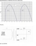
I really wish someone would post diagram #1004 in something other than photobucket.
- Location
- Wisconsin
- Occupation
- PE (Retired) - Power Systems
Not so.
One diode conducts from Va to N when Va is positive wrt N.
The other diode Vb to N when Vb is positive wrt N.
These two conduction periods occur at different points in time thus are not in phase.
I wouldn't call that relatively in-phase.
I'd call it anti-phase.
Rereading my answer, i can see where there may have been some confusion.
What did I say wrong?
One diode conducts while the current is flowing in the direction of A towards N and from N towards B. The other diode conducs at a different point in time, when the current is flowing from B towards N and from N towards A. Two different diodes two different conduction periods.
My second statement related to; if your voltages are relatively in phase with your currents.
Last edited:
No, the phase of one is (wt), the phase of the other is (wt), you just switched probe direction so your graph is inverted for the second.
Nonsense! Both V1n and V2n are defined relative to N, therefore they must be measured relative to N, and Besoeker's full wave rectifier would only be half wave if they were in phase. You demonstrate a poor understanding of what a reference is all about. You would do well to lay off the sniping!
- Location
- Wisconsin
- Occupation
- PE (Retired) - Power Systems
I really wish someone would post diagram #1004 in something other than photobucket.
View attachment 6493
Attachments
Last edited:
- Location
- Mission Viejo, CA
- Occupation
- Professional Electrical Engineer
It would work fine - it must, since the phaseIf the phases were identical the circuit in post #1004 wouldn't work.
But it does.
If you had quoted the phrase in full context (I underlined it):
The above quotation is correct. The phase of the transformer secondary voltages is not defined by the resultant current flows, whether conventional, rectified, clipped, "shaded-pole," etc. - or even none at all (open-circuited)....
Seriously, you acknowledge the frequency is the same ? that?s a start. Speaking of starting, while it may be a wild assumption, I believe you would probably agree the phasors started rotating at the same time. That means their periods are identical. It also means the characteristic phase of the voltage functions they inscribe can BOTH be written based on either (wt + 0) or (wt + 180) or (wt - 180) or (wt + 360) or (wt - 360) or, guess what, any other (ωt + Φ0) or (ωt - Φ0) you choose; i.e., the phases are also identical.
I'd prefer to stay out of the "oscilloscope-jungle"; I don't need an oscilloscope or a graphic from one to understand phase correctly. I only need the characteristic equation of the voltages being compared.
- Location
- Mission Viejo, CA
- Occupation
- Professional Electrical Engineer
I'm not trying to model power - I'm modeling transformer secondary voltages. Let's not drag in another red herring.Rbalex, I really wouldn't want to argue math with you. And I'm pretty good at math. Since they aren't setting the original equation up correctly they're never going to get the correct result. Voltage measurements are how we determine the direction of power flow and not the other way around. Reset your equations to model power and the two equations become (wt) and -(wt+180).
Um, first of all, Thanks Jim. I wanted to say that before:
:rotflmao:
What part of AC did Besoeker not understand?!?
In a single phase Alternating Current circuit: Power flows from top to bottom during one half of the AC cycle. Power flows from bottom to top during the other half of the AC cycle. There's only ONE cycle running across that coil. By any decent definition A thing is A thing not TWO things.
So we're arguing over this because some people can't understand that their circuit should be modeled for each peak like a DC circuit?
I'm not trying to model power - I'm modeling transformer secondary voltages. Let's not drag in another red herring.
Not a red herring. As long as you limit the discussion to voltage, Mivey wins. Because he's playing scarecrow to Dorothy. He's dropping a negative on you. But if you're gonna insist on voltage anyway, then model the equivalent DC circuits for T=90 and T=270. That should point out his inversions. He's using his neutral reference convention to measure both directions at the same time and claiming it's only one direction.
ex. If I face south the south pole is forward. If I face north the north pole is forward. Therefore both poles are "away" from me and therefore in a positive direction. Both are +(half a world away).
They're easy to equate. Fix your probe directions and they both become (wt). YOU are the one dropping negative signs. Instantaneous power flow is always in one direction across the entire coil. It doesn't reverse at the neutral. Measure with the power and you get (wt). Measure against the power and you get -(wt+180) or simplified (wt). There is no displacement to ignore. I CAN argue with your voltage description because it's a voltage gradient, A & B are not independent of each other not in anti-phase.
We do NOT switch probe leads. We leave the ground clip on N. As Bes says, we would knacker the scope if we put the ground clip on V1 or V2.
We do NOT switch probe leads. We leave the ground clip on N. As Bes says, we would knacker the scope if we put the ground clip on V1 or V2.
Of course you don't switch probe leads. Which is EXACTLY your problem. As I stated, you need to correct your probe DIRECTIONS if you want to see it correctly. "Away" is not a valid choice of direction for establishing "Positive". "Away" is pointing in two distinctly different directions like the scarecrow in the Wizard of Oz. As to knackering your scopes, try getting a better scope with isolated probes. Stop wearing Wal-Mart shirts in a fashion show.
- Status
- Not open for further replies.