Why is residential wiring known as single phase?

Status
Not open for further replies.

templdl

Senior Member
Location
Wisconsin
Well, I thought that I would drop in again to see if you have this world problem has been solved solved yet. Is it in fact single phase or more and is the jury still out to lunch or more correctly stated as in deliberation.
In the meanwhile I'll contemplate if I should mount my convenience outlets with the ground up of down.
 

rattus

Senior Member
Well, I thought that I would drop in again to see if you have this world problem has been solved solved yet. Is it in fact single phase or more and is the jury still out to lunch or more correctly stated as in deliberation.
In the meanwhile I'll contemplate if I should mount my convenience outlets with the ground up of down.

How about left or right, or N, S, E, or W?
 

Rick Christopherson

Senior Member
Mivey, I appreciate you taking the time to create the new graphic with superimposed signals. Unfortunately, as I said earlier, your example doesn't reveal anything different. It just makes it a little more difficult to see. Nevertheless, I owe it to you to take the time to show that.

I believe your assertion was that the V@120? voltage was feasible only by phase-shifting the other voltages. However, the reason why this does not prove anything is because you get the same result without any phase shifting. The transformations are no different than the single phase version I was discussing previously.

The following equations follow the direction convention as used in your two primary voltages (2V@0 and 2V@240) and their vector arrows:
V5n = -V12 - V56 = -V@0 - V@240 = -V@300

At this point it is still the same inversion that is used in the single phase example, and no phase shift is required. However, you can still apply the same mathematical inversion/phase transformation that you choose to use in the single phase system and reach the same result you show below. The difference is, that by acknowledging that these are inversions and not phase shifts, it explains why the anomalies don't shift in time with the apparent shift in the waveforms.

If they were real phase shifts and not just apparent, the anomalies would shift too.

Fair enough?

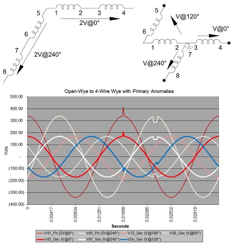
Ok, the graphic below shows what I asked you to try. You will notice that the artifact on the primary does not shift in time for the secondary waveforms. I have a different artifact for each primary winding and you can see how it shows up on the secondary. No time shift. But the red, white and blue secondary voltages have 0?, 240?, and 120? voltages. The 120? voltage is the result of phase shifting other voltages but there is no time shift in the delay or advance sense. Only if we compare the peak times of the waves do we talk about a time shift for the artifacts.

OpenWyewithAnomalies.jpg


PS: Good night. The guineas have long been in bed and I should be too.
 
Last edited:

mivey

Senior Member
At this point it is still the same inversion that is used in the single phase example, and no phase shift is required. However, you can still apply the same mathematical inversion/phase transformation that you choose to use in the single phase system and reach the same result you show below. The difference is, that by acknowledging that these are inversions and not phase shifts, it explains why the anomalies don't shift in time with the apparent shift in the waveforms.

If they were real phase shifts and not just apparent the anomalies would shift too.

Fair enough?
If they were phase shifts related to time shifts, the anomalies would move. But these are phase shifts related to physical shifts. These are also called phase shifts in our industry as shown by my references in #1744.

I probably could readily put my hands on 50 to 100 more references that use the same terminology but there is no way I'm going to take the time to do that. I have been in the electric and utility industry long enough to know that is what we call phase shifts by transformers.

Whether it is a 180? phase shift by inversion we use on the very front end to negate the 180? primary to secondary phase shift, or a phase shift due to taking voltages between different terminals and in different directions, they are still called phase shifts in addition to being called phase displacements and phase differences.

The phase shifts caused by physical shifts are not the same as phase shifts caused by time shifts. You do not have to agree with the terminology, but the physical shifts are also recognized to be phase shifts and that usage has been in place for a very, very, very long time and I doubt it is going to change now.

Fair enough?
 

rattus

Senior Member
Looks like Rick has wimped out on me.

Won't explain how a sine function can have two phases at the same time.

Can anyone else explain it?
 

__dan

Banned
Looks like Rick has wimped out on me.

Won't explain how a sine function can have two phases at the same time.

Can anyone else explain it?

Yes, connecting to the winding endpoints, you have a fixed voltage source between two terminals and so, a energy potential between the terminals. You are calling each terminal a different phase and hung up on a naming convention. As you step through the winding from one end to the other, each winding is matched in phase and so, is added in series and adds voltage between the terminals.

Adding a third terminal at the midpoint of the winding and placing your measuring device common at the center, this baffles you, as your measuring protocol takes the origin reference point at the winding center instead of at the winding endpoint. Now, stepping through the winding using center as the origin, the windings appear to have reversed their winding directions on your measuing instrument, when actually the windings have not changed. What has changed is a reversal of the polarity of the instrument leads relative to the winding turn direction. You see an artifact of your measuring protocol, not an actual reversal of the winding turn direction. The windings are fixed at the factory and wound in the same direction.

This is where sin(wt -+ 180) refers to the reversal of the polarity of leads of your test eqipment on connection to the actual. The 180 deg phase displacement is a special case of reversing polarity, magnitude, or displacement along the same line. Operating or moving along the same line, this special case is where the math reduces to a one dimensional solution and there is no projection or variation in any second dimension, such as the Y axis or the rotation of a phase angle. Rotating the phase angle by any amount other than 180 deg would require a two dimensional coordinate system and a projection or variation in that second dimension, such as the rotation of a phase angle.

Your partners introduction of actual phase shifts elsewhere in the system does not help relieve you of your uncertainty about what exactly is really going on.
 

pfalcon

Senior Member
Location
Indiana
Every sparky knows he's working with 2 phases in a standard residential panel, and better not get them mixed up! If I have to be careful with tandem breakers, and not getting my multi-wire legs on the same phase etc., how does "single phase" apply?

Because they pull off opposite ends of the same utility transformer (ie. one winding)? Because they cancel out on the neutral with 240V? Or is it a misnomer. I've always been curious about this.

Why it's called what it's called:
Declaration #1: In 120/240V systems, there is a single induction field from the primary generating a single reaction through the secondary coil. This is the SINGLE PHASE.
Declaration #2: In Delta/Wye et al systems, there are THREE induction fields from the primaries generating THREE reactions through THREE secondary coils, hence THREE PHASE.

Other discussions:
120/240 is typically measured from the center tap with the two halves referred to as legs. This creates numerous useful properties that people are compelled to name and label. This doesn't make any of them "wrong", they just don't apply to why it's called what it's called as stated above.

Conventions:
As a short label we'll call one end A (aka V1, X1), another B, and the center N (for neutral).
Ideal AC uses an ideal sinusoidal wave form we're all familiar with.
Also, traditionally we assign a phase start time t0 as the rising zero crossing of the sine wave.
And we typically assume N to be 0V for convenience.
And because we are who we are we then take measurements including

Voltages:
By physical reality, at t0 and every 1/2 cycle they're all 0V across the coil. At 1/4 cycle one end will have risen to +120V and the other will have fallen to -120V. At 3/4 cycle they'll reverse. In truth, from one end of the secondary to the other we have a voltage gradient. The proportion of the distance between any two probes compared to the overall length will yield a proportional voltage reading. Hence the 120/240V system is also called an AC Voltage Divider.

So, to arguments about phases:
Compelled as we are to have labels in order to speak about things, it's common practice to refer to the wave form generated by the voltage as a phase. Having no better word, and through common usage, therefore it is. Further, A and B generate phases with opposite polarity as referenced from N. It's important to note that these voltage phases have nothing to do with why the system is called single phase. There is still only one induction field present which is the phase that gives single phase it's name. But the English language is renowned for overloading words with multiple meanings.

Phase 1: The phase generated by the induction field that gives single-phase it's name.
Phase 2: The individual voltage readings that can be measured.
Phase 3: The individual current readings that can be measured.

Phase is an overloaded word just as the word duck is (duck beneath, also the water fowl). Therefore depending on which usage the poster is discussing may generate 1, 2, 4, 6, or infinite phases. All are legitimate answers depending on the usage in play. But only one usage gives the system it's name.
 

gar

Senior Member
Location
Ann Arbor, Michigan
Occupation
EE
120305-1005 EST

Consider the spinning disk watt-hour meter on the side of your house fed from a center tapped secondary of a single phase input transformer.

When you apply a resistive load between either leg and neutral the disk rotates in a positive direction indicating power consumption.

Take this same meter and supply it with a 240 v single phase input. Just a single coil single phase secondary. This means on the input side both current coils are connected together, and on the output side I can connect a resistive load to either output. What happens when you switch the load from one output leg to the other?

.
 

Rick Christopherson

Senior Member
The phase shifts caused by physical shifts are not the same as phase shifts caused by time shifts. You do not have to agree with the terminology, but the physical shifts are also recognized to be phase shifts and that usage has been in place for a very, very, very long time and I doubt it is going to change now.
I don't understand what it is you are calling a physical shift. Nothing is physically moved, so this does not seem to be an appropriate term. I've never heard the term before, so I don't think I could agree that it is industry standard. Nevertheless, even if something has a name by common convention, it doesn't make it what the label describes. Our industry has many examples of this, and as Rattus has pointed out, phase is one of them (as opposed to "leg" or some other term).

But more importantly, I am not levying an argument about naming conventions, because they are just that, conventions. I don't have a problem representing an inversion with a phase shift. That is quite common. What I take issue with is the distinction between a real phase shift and an apparent phase shift. Your own discussion even suggests when and why these are different. A real phase shift shifts the signal in time, but an apparent phase shift does not. This lack of a time shift is evident in the graphics that we both have now shown.
 

rattus

Senior Member
Yes, connecting to the winding endpoints, you have a fixed voltage source between two terminals and so, a energy potential between the terminals. You are calling each terminal a different phase and hung up on a naming convention. As you step through the winding from one end to the other, each winding is matched in phase and so, is added in series and adds voltage between the terminals.

Adding a third terminal at the midpoint of the winding and placing your measuring device common at the center, this baffles you, as your measuring protocol takes the origin reference point at the winding center instead of at the winding endpoint. Now, stepping through the winding using center as the origin, the windings appear to have reversed their winding directions on your measuing instrument, when actually the windings have not changed. What has changed is a reversal of the polarity of the instrument leads relative to the winding turn direction. You see an artifact of your measuring protocol, not an actual reversal of the winding turn direction. The windings are fixed at the factory and wound in the same direction.

This is where sin(wt -+ 180) refers to the reversal of the polarity of leads of your test eqipment on connection to the actual. The 180 deg phase displacement is a special case of reversing polarity, magnitude, or displacement along the same line. Operating or moving along the same line, this special case is where the math reduces to a one dimensional solution and there is no projection or variation in any second dimension, such as the Y axis or the rotation of a phase angle. Rotating the phase angle by any amount other than 180 deg would require a two dimensional coordinate system and a projection or variation in that second dimension, such as the rotation of a phase angle.

Your partners introduction of actual phase shifts elsewhere in the system does not help relieve you of your uncertainty about what exactly is really going on.

dan, the question was about sine functions. No mention of voltages or currents or transformer windings. Let me rephrase the question:

Consider the sine function sin(wt + phi0), just a simple trig function, not necessarily representing anything.

What is the phase of said function? Is it (wt + phi0)? Can you twist the math around to make the phase equal to (wt)? If you say you can, please justify your answer.
 

rbalex

Moderator
Staff member
Location
Mission Viejo, CA
Occupation
Professional Electrical Engineer
It's relevance is that the same 120-0-120 (or whatever voltage) arrangement is used.
All connected like six spokes of a wheel.

Here's a piccy:

Hexaphase03.jpg


Arrangement A is the usual residential arrangement. The one you want to call single phase.
Depicted in blue.

Arrangement B shows that exactly. Plus the exactly same arrangement from the other two of the three phases.

Yet it is a hexaphase arrangement. Hex. Six.
Working backwards from that, how do you get from six to one?
Bes I apologize for not responding earlier. I scrolled past this post, because I thought you were responding to someone else.

Basically as I explained to Gar in 1740, if you limit your described system to the voltages you indicated, assuming a common t0, all six voltage functions may still be written validly in terms reduced to ([ωt + φ0]), ([ωt + φ0]+ 120?) and ([ωt + φ0]+ 240?) or (not both) their equivalent inverses; i.e., it is still a simple three-phase system if you don't introduce EVERY equivalent inverse into the argument mix. What genuinely creates "hexiphase" is the secondary delta connections (line to line) that are also valid; whether you use them or not. Depending on the secondary connection, (DyN1 or DyN11) the additional three phases would be ([ωt + φ0]+30?), ([ωt + φ0]+ 150?) and ([ωt + φ0]+ 270?) or (not both) ([ωt + φ0]-30?), ([ωt + φ0]+ 90?) and ([ωt + φ0]+ 210?) or their equivalent inverses. Need I say you don't get to use them indiscriminately either.

While it was somewhat "tongue-in-cheek" at the time, my very first post in this thread (Post 132), said "The real question is not why residential voltages are called “single phase” but why Y-connected secondary’s of three winding transformers aren’t described as 'six-phase'" Including line to neutral and conventional line to line, you would get the same six-phases for the voltage functions in a more conventional wye connection.

BTW, Note, I have always started from a definition. It was like pulling teeth to get a counter-definition, (844) but read properly, the conclusion is the same.
 
Last edited:

rbalex

Moderator
Staff member
Location
Mission Viejo, CA
Occupation
Professional Electrical Engineer
Indeed, the trivial case, but what if phi0 = PI?
Nope can't do that; but I can make sin (wt) = 0 = sin(wt + pi). If you would just quit trying to indiscriminately swap the application, you might actually learn something new.
 

__dan

Banned
dan, the question was about sine functions. No mention of voltages or currents or transformer windings. Let me rephrase the question:

Consider the sine function sin(wt + phi0), just a simple trig function, not necessarily representing anything.

What is the phase of said function? Is it (wt + phi0)? Can you twist the math around to make the phase equal to (wt)? If you say you can, please justify your answer.

Math is loaded with periodic twisted functions and this does fascinate me. Can you be more specific? Care to discuss Fibonacci expansion and retracement?

wt is the period and phi0 is the phase constant. The sum (wt + phi0) is the phase, which is a time dependent function.

The sin function is the ratio of the opposite side of a triangle to the hypotenuse. For all values of y, when h != 0, the ratio y/h solves to a range of -1 to +1, or 0 to 360 deg, or 0 to 2pi radians. The phase is the instantaneous value of the ratio as a function of time, so this value naturally includes the period and the fixed phase constant.

Phase = wt for the case where phi0 = 0. Phi0 is a constant that is fixed and determined or provided to you by the system that you are observing. It can also be any fixed, arbitrary, reference point. If you reverse the polarity of your test leads, this has the effect of adding pi radians or 180 deg to the phase constant phi0. Note that this change to phi0 was caused by you and not by a change to the system under observation.

Similarly, as proposed by your partners, multiple and arbitrary changes to the system under observation can cause changes to the phase constant phi0. When you stop making arbitrary changes to the system under test, stop changing the parameters and definitions, phi0 will stop changing.

So, yes, I can also twist the parameters of the system under test, by either reversing the test leads of the instrument, or by other arbitrary means proposed, to change the phase constant of the resulting measurement, so that phi0 can be made to be any number that I choose.
 

rattus

Senior Member
Nope can't do that; but I can make sin (wt) = 0 = sin(wt + pi). If you would just quit trying to indiscriminately swap the application, you might actually learn something new.


Yes, sin(0) = 0 = sin(n*PI), but is that true for the general case? That is:

Is sin(wt) = sin(wt + phi0) where phi0 can be any value between 0 and 2PI?
 
Status
Not open for further replies.
Top