winnie
Senior Member
- Location
- Springfield, MA, USA
- Occupation
- Electric motor research
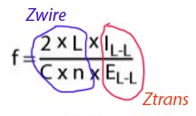
1000 feet of awg 1 has calculated inductance of 687000 nH or 0.000687 H see: https://www.allaboutcircuits.com/tools/wire-self-inductance-calculator/
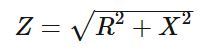
The inductive reactance is 2 pi f L... or 2 (3.141) (6) (0.000687) = 0.259 ohm http://www.66pacific.com/calculators/inductive-reactance-calculator.aspx
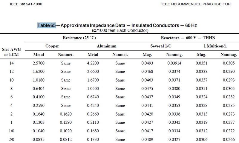
Why is the 0.259 ohm so far from the NEC listed value of 0.0046 ohm?
How does NEC derive the 0.0046ohm? Can you help derive 0.0046 ohm? I've been trying it for 2 hours already.
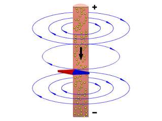
The key issue here is that circuit conductors are laying side by side with the corresponding return conductor; they are not single conductors in free space.
The magnetic field created by current flow in the conductors thus extends far less into free space.
Since self inductance is all about the magnetic flux created by current flowing in the wire interacting with the wire, when you have less magnetic flux you have lower inductance.
The larger the space between corresponding circuit conductors, the larger the inductance.
-Jon

")