You are using an out of date browser. It may not display this or other websites correctly.
You should upgrade or use an alternative browser.
You should upgrade or use an alternative browser.
3 phase to single phase
- Thread starter bfox561
- Start date
- Status
- Not open for further replies.
- Location
- Illinois
- Occupation
- retired electrician
Many 3 phase 4 wire systems are wye systems and the line to line voltage will be 208, not 240. If that is the case make sure your equipment is suitable for use on 208.
Rick Christopherson
Senior Member
I don't know if there are differences in terminology or not, but when I hear 3-phase, 4-wire, that means 3-hots and a ground. A 5-wire system would have the neutral.
If that is the case, you will need to derive the neutral with a center tap.
If the neutral is present, then as Roger pointed out, make sure it is not the high leg on a center tapped delta (120/240 3-phase). If it is a 5-wire wye system (120/208 3-phase), then you will have 120 volts phase to neutral and 208 volts phase to phase. If your charger doesn't like 208 volts, then you will still need to use a transformer.
Rick Christopherson
Senior Member
That would work, but it will give you only 208 volts phase-phase. No, you can't simply add the two 120 volt components to get 240 because they are not in-phase with each other.it is a 120v/208y 3 phase 4 wire panel. cant i just take two legs of 120 and use them to create the 240? i guess that would make it a 2 phase. i still need a single phase!
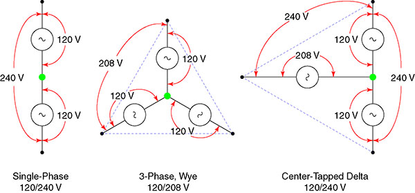
Here is a picture I use frequently for questions about system types.
it is a 120v/208y 3 phase 4 wire panel. cant i just take two legs of 120 and use them to create the 240? i guess that would make it a 2 phase. i still need a single phase!
The term Tech as a occupation always gives me pause.
Most electricians will refer to two legs as two of the lines, or phase A and B or derive 208 and use it as the line voltage rather than two legs of 120. 120 is a phase voltage in some 3 phase configurationsand and in single phase. Two phase (doubt you have it) could be three or 5 wire. I'm not sure if it was ever distributed in other arrangemenmts.
Roger and Don gave you some good info.
The eq must be able to function properly on 208. and if it will, you can thake two poles (lines, or phases) fromthe panel and feed the charger.
Last edited:
Generally when someone says "3-phase, 4-wire", they're referring to 3 phases and 1 neutral, not the ground, because technically you could have a system without a "wire" ground that uses bonded conduit as a ground if needed. The number of wires refers to the quantity of (normally) current-carrying conductors, which includes the neutral but not the ground.I don't know if there are differences in terminology or not, but when I hear 3-phase, 4-wire, that means 3-hots and a ground. A 5-wire system would have the neutral.
For the OP's 208Y/120-volt system, note that he said 3-wire, which means you'd run 2 phase conductors and 1 neutral (plus 1 ground). The requirement for the 3rd wire (neutral) tells me that there's probably a control section (independent of the main charging apparatus) that needs 120V and the equipment isn't deriving 120V internally, thus the need to run the neutral to have 120V in addition to the 240V.
Ultimately, you'll have to check the documentation or with the manufacturer to determine if it's okay to supply the 240V parts at 208V (and hopefully just charging slower than if they were served at 240V).
Rick Christopherson
Senior Member
Different parts of the electrical industry have different definitions, which is why I prefaced my first posting the way that I did.Generally when someone says "3-phase, 4-wire", they're referring to 3 phases and 1 neutral, not the ground....
- Location
- Wisconsin
- Occupation
- PE (Retired) - Power Systems
On a single phase 3-wire circuit a buck-boost will also affect the L-N voltage.Use a buck/boost transformer. Not that expensives and easy to do.
Gus
Rick Christopherson
Senior Member
I am a little confused by this Jim. If you install a 208:240 transformer on a 208 system, the L-L will be 240 and the L-N will be 120 from the center tap of the transformer. There will not be a phase angle between the lines and neutral.On a single phase 3-wire circuit a buck-boost will also affect the L-N voltage.
- Location
- Wisconsin
- Occupation
- PE (Retired) - Power Systems
That is true for a 2-wire 208V to a 3-wire 240V transformer.I am a little confused by this Jim. If you install a 208:240 transformer on a 208 system, the L-L will be 240 and the L-N will be 120 from the center tap of the transformer. There will not be a phase angle between the lines and neutral.
My statement was for a buck-boost transformer.
A 208/120V system would be boosted to 240/138V.
A 120/240V would would be bucked to 104/208V.
brian john
Senior Member
- Location
- Kilmarnock, Va
- Occupation
- Retired after 52 years in the trade.
All battery chargers I have had installed are 120 VAC ungrounded and grounded, 208/240 VAC single phase 2 wire with ground, 240 VAC single phase 2 wire with ground, 208 VAC 3 phase 3 wire with ground.
I have 30 chargers in my warehouse at present by a variety of manufactures all meet the voltage requirements above.
I have 30 chargers in my warehouse at present by a variety of manufactures all meet the voltage requirements above.
zbang
Senior Member
- Location
- Roughly 5346 miles from Earls Court
How many wires?
How many wires?
But I don't think that means a 3-phase 3-wire system doesn't have an EGC. I'd say that generally a grounding conductor is assumed unless specifically excluded. Does anybody do it differently? Of course, it does get confusing when you have 12/2 NM (with grounding conductor, 3 conductors total) and 12/3 SO (which also has 3 conductors). That really bothered me early on.
How many wires?
I don't know if there are differences in terminology or not, but when I hear 3-phase, 4-wire, that means 3-hots and a ground. A 5-wire system would have the neutral.
But I don't think that means a 3-phase 3-wire system doesn't have an EGC. I'd say that generally a grounding conductor is assumed unless specifically excluded. Does anybody do it differently? Of course, it does get confusing when you have 12/2 NM (with grounding conductor, 3 conductors total) and 12/3 SO (which also has 3 conductors). That really bothered me early on.
Rick Christopherson
Senior Member
It is not really my neck of the woods, but why would you connect the neutral on the line-side of a buck/boost? That just wouldn't make any electrical sense to me. Without the neutral on the line-side, you have just two electrical points, and there can be no phase angle between two points.That is true for a 2-wire 208V to a 3-wire 240V transformer.
My statement was for a buck-boost transformer.
A 208/120V system would be boosted to 240/138V.
A 120/240V would would be bucked to 104/208V.
As long as your buck/boost is connected line-to-line on the line-side, then the 3 output points (L1, N, L2) will always be single-phase and in-phase (e.g. 120/240). Right?
Rick Christopherson
Senior Member
But if you look at the recent thread on adding a panel to a detached garage, the specific distinction was that a 120/240 "3-wire" system was installed instead of a 120/240 "4-wire" system as required under code.But I don't think that means a 3-phase 3-wire system doesn't have an EGC. I'd say that generally a grounding conductor is assumed unless specifically excluded. Does anybody do it differently? Of course, it does get confusing when you have 12/2 NM (with grounding conductor, 3 conductors total) and 12/3 SO (which also has 3 conductors). That really bothered me early on.
As I understand it, the nomenclature you are using is actually referring to "nodes" or "poles", not "wires". But that is why I didn't want to make any assumptions. If the original statement was listed as a 3-phase, 4-pole system, you would know exactly what it was without guessing, and then the only remaining question is wye or center tapped delta.
- Location
- Wisconsin
- Occupation
- PE (Retired) - Power Systems
If you are wiring per the NEC, you can never have a 2-wire to 3-wire center-tapped buck-boost fed from a wye system.It is not really my neck of the woods, but why would you connect the neutral on the line-side of a buck/boost? That just wouldn't make any electrical sense to me. Without the neutral on the line-side, you have just two electrical points, and there can be no phase angle between two points.
As long as your buck/boost is connected line-to-line on the line-side, then the 3 output points (L1, N, L2) will always be single-phase and in-phase (e.g. 120/240). Right?
For the sake of discussion: N= system neutral and Nt= buck-boost neutral
Lh = high side line, and Ll low side line.
If the output of the 3-wire buck-boost is 120/240 (120V Lh-Nt) then the input side must measure 104/208 (104 Ll-Nt). This means the neutral point of the buck-boost is not the same as the neutral point of the system which is 120/208V). But because NEC 250.20(B) requires Nt to be grounded, it must be, electrically, the same point as as N or current will flow over the 'grounding' connection. If they are the same point then Ll-Nt must be 120V which means Lh-Nt must be 138V.
Rick Christopherson
Senior Member
Jim, if memory serves me this is your area of expertise, so please forgive me, but I cannot find anything in code that makes such a statement (Edit to add: requiring the line-side neutral connection). I also can't think of a single reason why code would want to make such an assertion. Could it be that you are referring to a 3-phase transformer connected to a wye system instead of this single-phase transformer?If you are wiring per the NEC, you can never have a 2-wire to 3-wire center-tapped buck-boost fed from a wye system.
This is a single-phase transformer connected across two phases of a 3-phase system, which creates a separately derived single-phase 120/240 volt system, and as such, it would require ground neutral bonding on the load-side.
Not only would requiring the line-side neutral completely negate the possibility of creating a 120/240 volt separately derived system, but part of me thinks this could create problems with a grounded conductor on both sides of a transformer, and each of them having their own grounding electrode system.
If I am off base, can you tell me which section of code I should read?
Last edited:
LarryFine
Master Electrician Electric Contractor Richmond VA
- Location
- Henrico County, VA
- Occupation
- Electrical Contractor
I have a problem with the Delta diagram: it shows the high leg as if the 208v was a source (a secondary.) In my opinion, they should show sources where the dotted lines are, and a dotted line where the 208v source is.Here is a picture I use frequently for questions about system types.
- Status
- Not open for further replies.