Transformer resistance

Status
Not open for further replies.

ronmath

Senior Member
Location
Burnsville, MN
Is there a way to calculate the DC resistance in ohms of a utility transformer line to line? It's a 1500 KVA transformer with 5.6%Z. The reason I'm asking is there is a piece of equipment downstream where the resistance must be a below a threshold. I can calculate that back to the transformer, but what would the transformer contribute?

Thanks!
 

zog

Senior Member
Location
Charlotte, NC
Is there a way to calculate the DC resistance in ohms of a utility transformer line to line? It's a 1500 KVA transformer with 5.6%Z. The reason I'm asking is there is a piece of equipment downstream where the resistance must be a below a threshold. I can calculate that back to the transformer, but what would the transformer contribute?

Thanks!

Do a winding resistance test. Only way to know for sure. Calculated may not be the same as actual.
 

mikeames

Senior Member
Location
Germantown MD
Occupation
Teacher - Master Electrician - 2017 NEC
You would have to know how long each winding is and then the the size and material of the winding conductor. It would be easier to just measure it with a meter.

Question: What is down stream that cares what the resistance is of an upstream transformer? Does it use the transformer for communication of some sort?
 
Last edited:

Mayimbe

Senior Member
Location
Horsham, UK
See if you can get the X/R ratio of the transformer. You got Z, with the ratio you could get the R value and the X value. If you cant get it, assume typical values (10% R and 90 % X, for example). Thats an aproximate way. Also, you can search the WORLD WIDE WEB for the short circuit test and no load test of that kind of transformers (1500 kVA, 14.4kV/480kV).

Search for the electric model of a transformer.
 

mivey

Senior Member
As has been pointed out, to know for sure you would have to measure it or obtain more data.

If you know the reactance, you can find the impedance. If you know the losses for the transformer, you can also find the resistance.

Without that data, we can only assume some values. Some loss data I have from GE would put the value at 0.0011 ohms on the secondary side.

Using GE approximate data:
Load Losses: 10850
Full Load Current = 1500 / sqrt(3) / 14.4 = 60.14 amps
R = Load Loss / 3 / I^2 = 10850 / 3 / 60.14^2 = 1 ohm primary

Full Load Current = 1500 / sqrt(3) / 0.480 = 1804 amps
R = Load Loss / 3 / I^2 = 10850 / 3 / 1804^2 = 0.0011 ohms secondary

Another way is to conservatively assume the transformer impedance has an X/R ratio of between 4 to 6 and using R = %R*10*kV^2/kVA and %X = %Z/sqrt(1+1/(X/R)^2)

So for X/R=4:
%X = 5.6/sqrt(1+1/16) = 5.43%
%R = %X/(X/R) = 5.43%/4 = 1.36%
R_secondary = 1.36*10*0.48^2/1500 = 0.00209 ohms

So for X/R=6:
%X = 5.6/sqrt(1+1/36) = 5.52%
%R = %X/(X/R) = 5.52%/6 = 0.92%
R_secondary = 0.92*10*0.48^2/1500 = 0.00141 ohms


I also have a table showing the GE approximate data for a 480 volt 1500 kVA distribution transformer with max primary line-line voltage of 18 kV is Z=5.75%, X=5.7%, R=0.72% (X/R=7.92). This yields:

R_secondary = 0.72*10*0.48^2/1500 = 0.00111 ohms
 

broadgage

Senior Member
Location
London, England
Are you quite certain that the DC resistance of the transformer is required ? that would be a most unusuall requirement.

Some specialist equipment draws large very brief pulse currents from the supply, in such cases the AC impedance of the supply is important, to ensure that the voltage does not drop too low during these brief heavy current pulses.
This might be called resistance, but is more correctly called impedance.
It would appear to me though, that the impedance of the service entrance conductors and feeders and branch circuit conductors, would also be required.
I dont see how any load, no matter how specialist, "knows" the difference between transformer impedance, and impedance elswhere in the circuit.

If it really is the DC resistance that is required, then this would have to be obtained by enquiry of the manufacturer, or by measurement.
The resistance will be too low to measure with a standard multimeter, a special 4 wire low range instrument would be required.
 

Mayimbe

Senior Member
Location
Horsham, UK
Are you quite certain that the DC resistance of the transformer is required ? that would be a most unusuall requirement.

Some specialist equipment draws large very brief pulse currents from the supply, in such cases the AC impedance of the supply is important, to ensure that the voltage does not drop too low during these brief heavy current pulses.

In a transformer, whats the difference between a DC Resistance and an AC Resistance???:-?


I dont see how any load, no matter how specialist, "knows" the difference between transformer impedance, and impedance elswhere in the circuit.

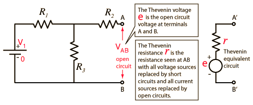
See Thevenin theorem. Equivalent Impedance.
 

mikeames

Senior Member
Location
Germantown MD
Occupation
Teacher - Master Electrician - 2017 NEC
theve.gif


That still does nto address the issue he stated.

Originally Posted by broadgage
I dont see how any load, no matter how specialist, "knows" the difference between transformer impedance, and impedance elswhere in the circuit.
 

arnettda

Senior Member
I am dealing with the same issues. Wiring a Ct at a hospital and comming out of my transformer I am above there specified amount. Not sure what I can do. Any help? Thanks


It's a piece of medical equipment that specifies what the max resistance line to line can be at the unit.
 

wirenut1980

Senior Member
Location
Plainfield, IN
I am dealing with the same issues. Wiring a Ct at a hospital and comming out of my transformer I am above there specified amount. Not sure what I can do. Any help? Thanks

I am beginning to see issues like this more and more. CT machine manufacturers are requiring ridiculous voltage tolerances that pretty much require the customer to buy a separate power conditioner for the machine.

I recently had a hospital with a Philips CT scanner failing components. An engineer at Philips told me that the cause for component failures was voltage sags wearing down components and causing them to fail, and I am not talking steady state sags, the sags were from utility faults and motor starts from a common subpanel, which are both short duration. The sags from the motor starts did get the voltage down to about 81% of nominal though...
 
Status
Not open for further replies.
Top