Single Phase VFD

Status
Not open for further replies.

LLSolutions

Senior Member
Location
Long Island, NY
Hey, this one is actually for my house. Has anyone ever come across a single phase 240v vfd? I've been going over ideas for new pool pump control. So far its a 2 speed motor or try to get A VFD. the pump would be 2hp.
 

IMM_Doctor

Senior Member
You Betcha!

You Betcha!

Amazing but true. There are new things of technology created everyday, and this one is ready, and on the market.

Check out Automation Direct.com They have VFDs with single phase input and generate three phase output.

We just installed one to reduce the speed of an fixed 3ph fractional horsepower industrial conveyor.
 

kwired

Electron manager
Location
NE Nebraska
The pump is a good application for VFD if the pump does not need to run at full speed all the time. The conveyor is not a good application for a VFD unless you actually need to vary the speed for some reason, if you don't need to vary the speed changing sheaves, sprockets, etc. to get the desired speed is better in the long run.

Single phase to three phase VFD's are not really anything new, VFD's in general are just coming down enough in price that they are more common than they used to be. DC drives used to be king of small variable speed motor drives. AC drives typically have more possibilities of what you can do with them and are taking over.
 

bpk

Senior Member
We use to install alot of Allen Bradley Powerflex series drives. I believe one of the parameters in the motor information setup of the drive was single or three phase output. Maybe someone else can confirm?
 
I found a few single phase 240 Volt VFD's in a quick search with 2 of my suppliers (online). My only suggestion would be to make absolute certain you allow air to circulate around the VFD enough that it will not overheat. That can be tricky if you are installing it in a 3R, 4X, or similar location.... maybe a VFD that small will not get very warm at all.....
 

sgunsel

Senior Member
You probably won't find a single phase output VFD. Most single phase motors likely to be used for a pump have starting circuits that are not compatible with a VFD. A typical single phase motor has a start winding that is disconnected by a mechanical centrifugal switch when the motor reaches a predetermined speed. So the motor must be run up to near normal operating speed for the starting switch to disengage. When the speed drops, the starter switch engages automatically. Not good for VFD or motor. Three phase motors do not require a starter winding.

If you want speed control, you should consider replacing the singe phase motor with a three phase motor. I did that on my furnace blower and am very pleased with the results. Up to 1 HP can be handled with 120 VAC single phase power, above 1 hp you will need to go to 240 VAC single phase.
 

norcal

Senior Member
The trouble I'm having is finding a "single phase in / single phase out"

That is because VFD's are 3? output only, & only for 3? motors, they are quite reasonable in price up to 3 HP w/ a 1? input & even avail w/ 120V input up to 1 HP.
 

charlietuna

Senior Member
Contact drive manufacturers - it may require a special order, but they make them. Consider now how many residential A/C units run on variable speed and the manufacturer would just have to install it in an enclosure. Toshiba made us one for a cooling tower model we made to explain the benifits of VFD's on cooling towers to building managers. Also you should try to find out the data(graphs) on the pump to see it's maximum efficiency speed and match that to the drive. You will save near 50% of operational costs plus your pool will stay cleaner
 

winnie

Senior Member
Location
Springfield, MA, USA
Occupation
Electric motor research
An electronically commutated 'DC' motor is essentially a 3 phase synchronous AC motor.

A VSD designed for running a 3 phase induction motor won't run an ECM 'DC' motor, but I'm sure that with suitable control inputs one could do so.

The reason that it is called a DC motor is that the switching is controlled by rotor position sensors rather than an external frequency control, so the motor acts very much like a brush commutated DC machine.

-Jon
 

kwired

Electron manager
Location
NE Nebraska
An electronically commutated 'DC' motor is essentially a 3 phase synchronous AC motor.

A VSD designed for running a 3 phase induction motor won't run an ECM 'DC' motor, but I'm sure that with suitable control inputs one could do so.

The reason that it is called a DC motor is that the switching is controlled by rotor position sensors rather than an external frequency control, so the motor acts very much like a brush commutated DC machine.

-Jon

I do not know much about how ECM motors work but have run into one that failed once. Out of curiosity I had to open it up. I know it had permanent magnets in it (in the rotor if i recall) That is what failed - magnet pulled loose and broken) I kind of assumed that DC current was used in the field windings since there are permanent magnets in the rotor. I can understand that the controller could likely sense the position, direction, and or speed of the magnet(s) and regulate the field accordingly to get the desired output speed.

I am certain it is definately not an induction motor like would be used on most VFD's. And similarities are likely about the same similarities as a DC permanent magnet motor is to an induction polyphase motor.

I can see it being able to achieve synchronous speed but don't see it as being like a three phase motor, unless you can provide more insight as to why it is like that.

Add:
I may need to refresh my memory of what exactly is synchronous speed. I'm pretty sure I know what it is with typical induction motors, don't know if the term even applies to DC or wound rotor motors. I always understood that these types of motors if not for mechanical limits like friction, loading, etc. would continue to increase speed while they were running, Where the top speed of an induction motor disregarding losses is limited by the speed of the rotating field
which will remain constant as long as frequency and voltage remain constant.
 
Last edited:

hurk27

Senior Member
I do not know much about how ECM motors work but have run into one that failed once. Out of curiosity I had to open it up. I know it had permanent magnets in it (in the rotor if i recall) That is what failed - magnet pulled loose and broken) I kind of assumed that DC current was used in the field windings since there are permanent magnets in the rotor. I can understand that the controller could likely sense the position, direction, and or speed of the magnet(s) and regulate the field accordingly to get the desired output speed.

I am certain it is definately not an induction motor like would be used on most VFD's. And similarities are likely about the same similarities as a DC permanent magnet motor is to an induction polyphase motor.

I can see it being able to achieve synchronous speed but don't see it as being like a three phase motor, unless you can provide more insight as to why it is like that.

Add:
I may need to refresh my memory of what exactly is synchronous speed. I'm pretty sure I know what it is with typical induction motors, don't know if the term even applies to DC or wound rotor motors. I always understood that these types of motors if not for mechanical limits like friction, loading, etc. would continue to increase speed while they were running, Where the top speed of an induction motor disregarding losses is limited by the speed of the rotating field
which will remain constant as long as frequency and voltage remain constant.

We had some very large 500hp DC synchronous motors on a very large extrusion presses where I worked in Sanford, Fl. they used a DC field and an AC wound rotor, also I have worker on a few cranes with DC synchronous motors on them, in both cases the field voltage was change to adjust speed, as well as ramp up, and slow down. Changing the AC frequency would also change the speed, so they could be controlled by both methods?
 

norcal

Senior Member
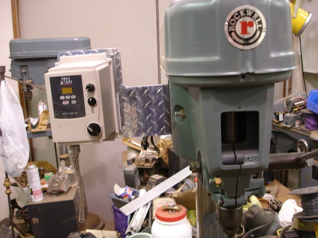
Since the OP mentioned this was for home use here is a pic of a Rockwell/Delta drill press w/ a 1/2 HP 3? motor w/a then unwired Teco 1 HP 230V NEMA 4X drive. (Rockwell used some odd frame motors so a VFD was simpler).

DSC03156.jpg
 

winnie

Senior Member
Location
Springfield, MA, USA
Occupation
Electric motor research
I doubt that anyone discussing this thread has used a true DC motor. I know that I have not. While true DC motors exist (search term: homopolar motor), all common motors in use have alternating current involved somewhere.

A classic brush commutated DC motor uses DC power, and has DC in the field coils, but uses the commutator to _make_ AC for the rotor. The current flowing in the alternator coils is alternating. Because the commutator is physically attached to the rotor, the AC in the rotor is tied to the specific position of the rotor, and held in proper relationship to the DC magnetic field created by the field coils or the stator magnets.

Imagine turning this motor 'inside out', putting magnets or a DC field coil on the rotor, and then using a mechanical commutator to alternate the current in the stator winding. The stator winding would generate a rotating magnetic field that was mechanically held in proper relation to the rotor's magnetic field.

This is essentially what is done with a brushless 'DC' motor. You have a rotor with permanent magnets which create a magnetic field. You have a three phase stator winding which is essentially similar to the three phase winding of a common induction motor. You have rotor position sensors which are used to control the switching of the control transistors. The drive transistors switch on and off in response to the rotor position, thus the AC in the stator in a brushless DC motor is tied to the specific position of the rotor.

The only essential difference between a brushless permanent magnet DC motor and a permanent magnet AC synchronous motor is how you decide when to switch the drive transistors. If you switch the transistors based on rotor position, then you call it a 'DC' motor. If you switch at a control frequency, then you call it an 'AC' motor.

In any case, this is off topic for the original question. I agree with others on the 'single phase in, single phase out' question: once you have the VSD, it is trivial to take single phase input and create 3 phase output, so for any sort of significant power level, a three phase motor is used on the output side. Large single phase motors are designed for single frequency operation, and won't take kindly to variable frequency.

-Jon
 

TxEngr

Senior Member
Location
North Florida
Whether you can buy what you want depends on the type of motor you buy. Certainly a 3 phase motor will work as you can see from earlier posts. If the motor is a permanent split capacitor or a shaded pole motor, a triac based speed controller may work. You would need to confirm with the motor manufacturer the application. You are also limited to the maximum ampacity you can use with these as well.
 

charlietuna

Senior Member
I am talking single and three phase induction motors and have installed many drives on many applications including pumps.
 

kwired

Electron manager
Location
NE Nebraska
I am talking single and three phase induction motors and have installed many drives on many applications including pumps.

Not on a standard capacitor start motor without some modifications.

I have seen variable speed drives for capacitor start submersible pump motors but the control box containing starting capacitor and potential relay is replaced with the drive and it controls voltage, and frequency the motor windings receive.
 

LLSolutions

Senior Member
Location
Long Island, NY
Ended up buying a 3 phase motor and a teco fm50 3hp vfd, seemed much easier than trying to find a single phase motor that didn't have dual windings for startup. the vfd came in 2 days still waiting on the pump before i can play.
 
Status
Not open for further replies.
Top