indirectly electrical

Status
Not open for further replies.
Location
NE (9.06 miles @5.9 Degrees from Winged Horses)
Occupation
EC - retired
Customer has a booster pump at the end of a 2" copper water line. Operational pressure at the input side of this pipe is 95 psi. Pump is rated at 145GPM @ 35 psi. Spray nozzles will use 34 GPM @ 40 psi.

What I need to know is how many gpm will thiis 2" pipe allow to flow.

They want to use a pressure switch on the input of this pump to turn it on. We have that done. but I believe the pump is starved for input water becase we do not get a significant pressure increase. My job is to fix it.
 

ZinskI/E

Member
Location
New Orleans, LA
I think you should consult a mechanical engineer for this. Max flow through a line depends on a number of factors, including pipe friction as installed.

IMO if you are concerned about the available pressure at the pump's inlet, you may want to consider a second switch. I assume the switch you mention is to start the pump when a low pressure condition exists downstream of your primary and booster pumps. The second switch would be a low pressure switch, either an interlock or alarm ensuring that the NSPHa does not drop below the pump's curve, thus preventing cavitation.

Depending on the install, it may be beneficial to utilize a pressure transmitter rather than the switches. The PT would provide a more informative and more configurable installation.

Be sure you have both pump curves available as well as the process temperature if/when you consult with a mechanical expert.

Good luck!
 

iceworm

Curmudgeon still using printed IEEE Color Books
Location
North of the 65 parallel
Occupation
EE (Field - as little design as possible)
What I need to know is how many gpm will thiis 2" pipe allow to flow.

I believe the pump is starved for input water becase we do not get a significant pressure increase. My job is to fix it.

Well, my favorite references for DIY hydraulic engineering calculations are:
Crane Technical Paper 410
and
Cameron Hydraulic data

ice
 
Location
NE (9.06 miles @5.9 Degrees from Winged Horses)
Occupation
EC - retired
There is an electrical solenoid valve ahead of the booster pump that supplies water to the pump. Once this pressure is up then the booster pump is suppose to turn on. I feel this valve is restricting flow and from what my more learned though less handsome brother has told me this evening, I should have in excess of 300 gpm available. I haven't seen the chart yet.
 

sabatini

Banned
Hello,
Friend what a nice sharing. I like your post. I am a newbie for this forum site.
Thanks for this nice sharing.
 

USMC1302

Senior Member
Location
NW Indiana
I'm with your less handsome brother, while there are a lot of factors that can be in play, I'd be thinking somewhere around 325 GPM should be available.
 

Smart $

Esteemed Member
Location
Ohio
Customer has a booster pump at the end of a 2" copper water line. Operational pressure at the input side of this pipe is 95 psi. Pump is rated at 145GPM @ 35 psi. Spray nozzles will use 34 GPM @ 40 psi.

What I need to know is how many gpm will thiis 2" pipe allow to flow.

....
Here's what I came up with for potential at input...
95psi is equal to 219.138ftH20
Velocity = √(2P) = √(2?219.138ftH20) = 20.935ft/sec
Cross-sectional area = pi?r? = 3.14...?(2/2)?in? = 3.142in?
3.142in? ? 144in?/ft? = 0.02182ft?
0.02182ft? ? 20.935ft/sec = 0.4567ft?/sec
0.4567ft?/sec ? 60sec/min = 27.40ft?/min
27.40ft?/min ? 7.48gal/ft? = 205.0gpm

However, this assumes a dynamic pressure of 95psi at input...because you said operational pressure. If that number was static pressure, the potential at input will likely be less.

Additionally, assuming a dynamic pressure of 95psi, this also means this is the potential as if there were a 2" hole at the point of input rather than a 2" pipe with restrictions downstream. You did not say how much length of 2" pipe (or tubing), or how many elbows or bends or change in elevation between input and output, or the location of the booster pump in the run.

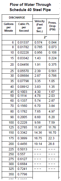
FWIW, a chart I have that's titled "Flow of Water Through Schedule 40 Steel Pipe" in The Control Valve Handbook published by Fisher-Emerson shows 2" to the have a practical upper limit at 200gpm with a flow velocity of 19.14ft/sec and a pressure drop of 28.8psi/100ft.

While a booster pump will help overcome pressure drops in the run and even provide an output pressure which exceeds pressure at the input, you cannot, however, achieve an output which exceeds the max volumetric flow rate at input...

That said, I had heard somewhere that the majority of the control valves used in the US are undersized.
 
Last edited:

charlie b

Moderator
Staff member
Location
Lockport, IL
Occupation
Retired Electrical Engineer
Something is not making sense here. Several things, in fact.

First of all, if you push 34 gpm of water through a 2? line, you will get a pressure drop of about 2 psi for every 100 feet of pipe. So if there is 95 psi available at the source, and you need only 40 psi at the nozzles, then a 2? line would have to be nearly a half mile long before the pressure drops from 95 to 40. In other words, if the pipe is shorter than a half mile, then you don?t need a pump at the end of the line, in order to give the nozzles what they need.

Secondly, if a pump can push 145 gpm at 35 psi, then it will push something like 130 gpm at 40 psi. That is way more than the nozzles need. So the pump appears to have been improperly selected.

Finally, if the pump is not delivering a differential pressure to the water system, then either it is spinning backwards, or there is a blockage in the nozzles, or a valve is closed somewhere.

To directly answer your question, a 2? line is well sized for a flow rate of 34 gpm.
 

lakee911

Senior Member
Location
Columbus, OH
second switch would be a low pressure switch, either an interlock or alarm ensuring that the NSPHa does not drop below the pump's curve, thus preventing cavitation.

I was under the impression that the pump's curve is exactly that ... there isn't any below the curve, above it, falling off, etc...
 

Smart $

Esteemed Member
Location
Ohio
First of all, if you push 34 gpm of water through a 2” line, you will get a pressure drop of about 2 psi for every 100 feet of pipe...
May be even less than that. I don't know where you got that number, but for steel pipe it is 1.05 psi drop per 100 feet at 35gpm...

FlowofWatertable.gif
 

iceworm

Curmudgeon still using printed IEEE Color Books
Location
North of the 65 parallel
Occupation
EE (Field - as little design as possible)
Pump is rated at 145GPM @ 35 psi.

Spray nozzles will use 34 GPM @ 40 psi.

I should have in excess of 300 gpm available.

I'd be thinking somewhere around 325 GPM should be available.

you have lost me. There is a bunch of stuff here that doesn't fit. From your description:
A 95psi source (unlimited volume available) is feeding one end of a 2" Cu pipe (unknown kength, unknown number of 90s)

to a valve (Cv unknown)

to a pump (NPSH unknnown)

to a nozzle reqireing 34gpm at 40psi
----------------------
Here are the parts that don't make sense:

If the end use is 34gpm, why would one need 300+gpm available at the booster pump inlet?

The booster pump is probably about 5hp. 34gpm at 40psi mabye takes a 2hp - 1.5 might be fine. Why the big pump? (the answer for this one one is likely, "Cause that is what is installed.")

A normal run-of-the-mill ASCO electric 2' globe valve has a Cv of 43. That will give less than 1psi pressure drop at 34gpm. I would not think that is dropping the pump suction pressure below its NPSH.

However, a 1000 feet of 2" CU pipe and a dozen 90s could well have a significant pressure drop. And, of course, we don't know what the pressure drop is on the 95 psi when the system is drawing 34gpm

I'm mostly just curious about the outcome.

ice

edit to add: I'm a slow responder - people keep interupting me with work. Most all I covered was covered by charlie, smart, lake, and pton
 
Last edited:

charlie b

Moderator
Staff member
Location
Lockport, IL
Occupation
Retired Electrical Engineer
May be even less than that. I don't know where you got that number, but for steel pipe it is 1.05 psi drop per 100 feet at 35gpm...
I got it from my local friendly plumbing engineer, who got it from one of those "sliding wheel design tool thingies" (we have similar sliding tool thingies for motor design and other electrical stuff). Does your source have a table for copper pipe, similar to the schedule 40 steel pipe?


iceworm

Curmudgeon still using printed IEEE Color Books
Location
North of the 65 parallel
Occupation
EE (Field - as little design as possible)

"Table 7-10 (for galvanized iron pipe) and table 7-11 (for copper tubing) may be used with the maximum fixture demand and the factor of simultaneous use to find the correct size of pipe for water-service lines. The minimum practical size for a water-service line is 3/4 inch. This size should be used even when calculations show that a smaller size could be used."

Not much information on this table. It is designed to give one a nominal flowrate and nominal distance that will still have enough pressure (nominal) to operate plumbing fixtures. It doesn't give any pressure drops, only goes up to 1" and does not account for the restriction caused by any 90s or other fittings.

Surely someone has access to a Crane TP 410? I have one at home - not at this office so I'm no help.

Charlie - how about your friendly local plumbing engineer?

ice
 

charlie b

Moderator
Staff member
Location
Lockport, IL
Occupation
Retired Electrical Engineer
try here charlie b
That reference talks about copper tubing. The OP is talking about copper pipe. The difference between tubing and pipe is like the difference between schedule 40 and 80 PVC.
Surely someone has access to a Crane TP 410?
I have one at my desk, and I looked at it before going to talk with my friendly local plumbing engineer. But I wasn't able to get any applicable formulas or tables in the short amount of time I had available. Besides, I haven't used that book since it helped me solve one of the problems in my PE exam. That was in 1987! :cool:
 

hardworkingstiff

Senior Member
Location
Wilmington, NC
I'm not as smart as you guys, but I just wanted to ask, is it really not working properly? I was taught you can't trouble shoot fluid systems (I was in the fuel business, like gas station pumps) without pressure gauges.

So, 1st question is, when the nozzles are dispensing fluid and the pump is off, what is the pressure on the inlet side of the pump and what is it on the outlet side of the pump? 2nd question is what happens to the pressures when the pump is turned on. That information I believe can tell you a lot.
 
Location
NE (9.06 miles @5.9 Degrees from Winged Horses)
Occupation
EC - retired
I have no pressure gauge immediately after the valve. Pressure gauge at outlet of booster pump reads zero on a 0-60 lb gauge with water on, no pump. With pump the gauge reads about 9 lbs. Gauge is new (unused) out of box but I have not confirmed its accuracy. Next week they have some down time for checks.
 

charlie b

Moderator
Staff member
Location
Lockport, IL
Occupation
Retired Electrical Engineer
Pressure gauge at outlet of booster pump reads zero on a 0-60 lb gauge with water on, no pump.
If the pressure source is 95 psi, you would need a couple miles of 2" copper pipe in order to drop the pressure to zero. Something is not adding up here.


How long is the pipe? Is it visible througout its length (i.e., can you tell that it is not ruptured in the middle, so that all the water is leaking out before it can get to the pump)? Is there a significant difference in elevation from the source to the pump? Is there any way to verify the pressure at the begining of the copper pipe, or the flow rate being supplied to this pipe from the source? Are they actually getting any water coming out of the nozzles?
With pump the gauge reads about 9 lbs.
That makes perfect sense, given that the pressure at the pump suction is near zero. The pump does not have the minimum net positive suction head (NPSH) necessary to allow it to move water.
 

hardworkingstiff

Senior Member
Location
Wilmington, NC
I have no pressure gauge immediately after the valve. Pressure gauge at outlet of booster pump reads zero on a 0-60 lb gauge with water on, no pump. With pump the gauge reads about 9 lbs. Gauge is new (unused) out of box but I have not confirmed its accuracy. Next week they have some down time for checks.

If it was my job, I would get the inlet and outlet pressure gauge readings with the pump off and with the pump running (of course with fluid being dispensed). You should probably also know what the inlet/outlet pressures are with no fluid being dispensed. IMO you can't even begin to trouble shoot the problem without this information.

Also, if the inlet pressure with the pump running is 0 you may need to install a vacuum gauge on the inlet side also.
 
Status
Not open for further replies.
Top