how do you measure inrush current?

Status
Not open for further replies.

wptski

Senior Member
Location
Warren, MI
I wish we had more time to edit our recent posts...

Ok, I went and did some tests with my Agilent (U1211A). It turns out the instructions have some errors in them, namely, the peak function does capture inrush and not voltage only, which I'll notify them about. I used all the different methods of capture (peak, recording min/max/avg and the regular reading you get in A mode.

Here's what I did: I took a 1500W Pelonis Disc heater then an old motor that's laying around and I set the clamp on the hot wire. I got the regular reading with heater or motor running, then the peak reading while plugging them in, then max/min/avg for each by allowing the meter to settle to close to zero A then plugging in the load and letting it run.

Heater:

Running load in regular A mode = 12.49A
Peak function (Inrush) = 45.60A
Min/Max/AVG = 0.06A/32.45A/ N/A (updates the longer the unit is running)


Motor:

Running load in regular A mode = 3.83A
Peak function (Inrush) = 16.75A (also as high as 24.55A, possibly depends on where the sine wave is at startup?)
Min/Max/AVG = 0.06A/4.33A/ N/A (same as above)


From these results I'd say my clamp has a min/max/avg sample rate that's much lower than what it uses during the peak measurements since the max readings are never nearly as high as the peak readings. I wouldn't assume that other meters will do the same with similarly named modes. I am going to contact Agilent and ask what exactly it's doing in Peak mode.
You can set it to trigger at a certain level of current. Like the Fluke 43B mentioned above which I have also doesn't start to record until tiggered. This is the way Fluke 337 also mentioned works also. Is there a difference between just plugging them in and waiting for a trigger to start the recording?? Not sure but that's the way Fluke and AEMC equipment work that measure inrush.
 

ELA

Senior Member
Occupation
Electrical Test Engineer
A finer detailed look using an oscilloscope

A finer detailed look using an oscilloscope

110109-1745 EST

To repeat some points I have made in various threads.

Instantaneously the current thru an inductor can not change.

From my statement above that one characteristic of an inductor is that the current can not instantaneously change this means that at the instant just after the switch is closed the current will still be zero. However, starting at that point, t=0, the current does start to rise. The voltage across the R and L instantaneously rises to the battery voltage, and also this is the instantaneous voltage across the ideal inductor because current is 0.

The rate of rise of current is determined by the L/R ratio. For a fixed resistance the larger L is the slower is the current rise, and vice versa. These experiments are simple to run with an oscilloscope.

.

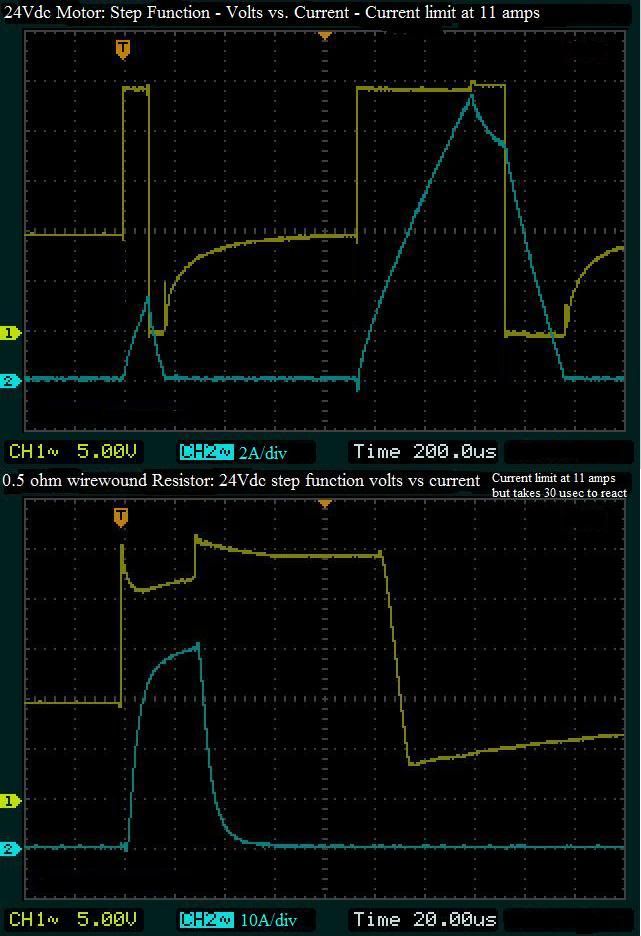
Here is a picture to help visualize what Gar has emphasized. The fact that "inrush" current in a motor does not occur instantaneously.
CompareResistortoMotorIramp.jpg


These show the advantage of sampling at a much faster rate using an oscilloscope. If you were sampling much slower the current might appear to rise instantaneously. When sampling fast enough you can see that it does indeed take some finite time for the current to rise.
These were tests done on a 24Vdc motor with a LRA of 44 amps. A current limited power supply was being used and set at ~11 amps.

In the top test you can see that when the pulse applied was very short the current does not reach a very high value. A second longer pulse is applied and the current rises until the set current limit value was reached. (still lower then locked rotor)

The bottom figure shows a wirewound resistor of approximately the same "DC" resistance value as the motor. NOTE: time and amperage scales are different from top view"
Here the rise time of the current is much faster and helps illustrate the effect of the motors larger inductance.

Although these tests were done on a DC motor they demonstrate what you might see if you were taking a very close look at an AC motor energized near a peak of the sinewave.
 

wptski

Senior Member
Location
Warren, MI
The intergration time list for the Fluke 337 is 100ms. I have a AEMC F05 and after measuring inrush, you can select between .5, 1, 2.5, 5 and 10 periods or cycles/hertz. Some clamp meters use 10ms IIRC. Seems like nobody agrees!
 

PetrosA

Senior Member
This thread showed me a few holes in my own knowledge so I contacted the product program manager at Agilent Handheld for some answers. I asked about the Peak and MinMax functions of the U1210 series clamp meters in specific, but he seems to think that certain methods and limitations will apply regardless of whose product we use. He was kind enough to read this thread and offer the following:

The Peak feature on the Agilent is equivalent to the Inrush feature of Fluke (et al.) and is sampling at 1ms intervals looking for the highest transient reading. It does not perform an RMS conversion for this measurement. Repeatability for this measurement is affected by the current waveform at the time you turn on the load so you're likely to get a different reading each time.

The MinMax recording feature does provide an RMS conversion, samples for a longer period of time and is what will show things like motor starting current more accurately.

He also agreed with ELA and Besoeker that sometimes a graphic profile of both inrush and starting current is needed and at that point an oscilloscope is necessary.

Hope this helps.
 

BJ Conner

Senior Member
Location
97006
Honeywell Visicorder

Honeywell Visicorder

I have seen an "amp-clamp" meter that had an "inrush" button.

My questions are,

Does the "min/max" button on ($100-200) amp-clamp meters function the same as the "inrush" button?

Will the "min/max" measurement of ($100-200) amp-clamp meters even be close to the actual inrush current of, for example, a 5HP motor starting?

Wayback we us to use Honeywell Visicorders.
http://www.recycledgoods.com/products/Honeywell-1858-T790G-Visicorder-Oscillograph-w-plug-ins.html
You hooked up the CTs to inputs, wired a start signal to motor start signal and pushed the button. Visicorders would shoot out a stream of paper with a large scale. ( like 1 cycle = 12" of paper). You had to make sure the thing was full fo paper or you could run out. It could fill up a room with paper if it had enougn in it.
There has to be a soft ware equivalent out there. :roll:
I would call one of the instrument rental places and see what they had. This is not a new wheel, it been invented many time before.
 
Status
Not open for further replies.
Top