3 phase load calculation

Status
Not open for further replies.

tryinghard

Senior Member
Location
California
Nothing wrong with using 100% of nameplate MCA if you wish - you will not be too small with your feeder size. Like I said before this is for sizing the branch circuit (an individual load). 440.3 refers you back to 430 for anything not modified by 440. Sizing feeders is not covered in 440 so you have to go back to 430 rules for sizing feeders.
Sure but ironically 430 has no significant change in the feeder size method 430.25, 430.24 ? non that I see anyway.

Lets say we have nine of the mentioned unit 1 connected to a 208 volt 3 phase source and was balanced across phases?

The more units you have the more that extra 25% of each compressor will add up if using the MCA for feeder and service calculations.
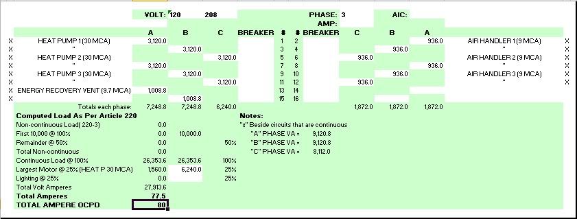
True, I notice using the 29 MCA example with 9 units:
246.4 amps - 1 largest motor at 125%
301.4 amps - MCA method
And with 3 units:
84 amps - 1 largest motor at 125%
100 amps - MCA method
 

tryinghard

Senior Member
Location
California
?A "best" balancing method must take power factors into consideration, especially when you have varying types and quantities of 2-pole loads on 3? systems?
I believe the MCA includes the power factor. In my opinion this MCA divide by 208v 1? equals a value that really is a misnomer called volt amps but it is a value that can be used to balance and calculate the full panel load or feeder load.

This 1? fed from 3? 208 is very curious though I think it usually occurs on existing building adding on or modifying (sounds like a new topic)
 

Smart $

Esteemed Member
Location
Ohio
I believe the MCA includes the power factor. In my opinion this MCA divide by 208v 1? equals a value that really is a misnomer called volt amps but it is a value that can be used to balance and calculate the full panel load or feeder load.
Using volt-amperes is the prescribed NEC unit for calculating service and feeder loads... and the reason this unit is used is because including power factor (or phase angle) into the calculation can make it very and unnecessarily complex. Also, volt-amperes is a always more than watts and accounts for current which flows through conductors but not converted to another form of energy yet still is a contributing factor to heating of conductors, the main cause of insulation degradation.

If we sized for watts (which is saying power factor is taken into consideration), we would likely have to bump up the 125% factoring to a higher percentage, or use some other means to account for the current which is not consumed. In the end we could balanced the loads better, but the more complex calculations necessary to do so would seldom justify the extra work.

This 1? fed from 3? 208 is very curious though I think it usually occurs on existing building adding on or modifying (sounds like a new topic)
I don't see how additions versus new construction make a difference. It's all in the hands of the system designer. I would have assumed predominance only for additions when the service is upgraded from 1? to 3? and the 1?, 2-pole loads pre-exist the upgrade.
 

tryinghard

Senior Member
Location
California
Using volt-amperes is the prescribed NEC unit for calculating service and feeder loads... and the reason this unit is used is because including power factor (or phase angle) into the calculation can make it very and unnecessarily complex...
I agree I thought you were advocating using power factor, although I think you were talking about balancing using amperes and I am talking about using a load calc method like a panel schedule.:)

I don't see how additions versus new construction make a difference. It's all in the hands of the system designer. I would have assumed predominance only for additions when the service is upgraded from 1? to 3? and the 1?, 2-pole loads pre-exist the upgrade.
Maybe but I have one in view right now that is an upgrade without additions to the building, it has existing multiple sized 1? & 3? panelboards fed from upgraded 3? 600A MDP receiving new service as 208 from 240.
 

tryinghard

Senior Member
Location
California
Huh?


I don't think Iwire's question was answered
The original poster wants to know the panels main breaker size and feeder size for said 1? equipment supplied from 3? 208. One HVAC unit at 30 MCA = 6,240VA half of this would occur on each lug of its supplying breaker and so on for each load resulting in a 74.6A calculated load, post 20
 

kwired

Electron manager
Location
NE Nebraska
This 1? fed from 3? 208 is very curious though I think it usually occurs on existing building adding on or modifying (sounds like a new topic)

It happens all the time in apartment buildings supplied by 120/208 three phase with a single phase feed to individual units, or a hotel supplied with three phase but you have all those individual HVAC units in each room, some even have single phase cooking equipment. There are other places too these are just a couple of the most common. I hooked up some cove heaters in a hospital more recently and had to balance them across three phases for best performance (they were not all same size). I have never seen a three phase cove heater, or baseboard heater. They are not large enough load as individual units that it is necessary to make them that way.
 

Smart $

Esteemed Member
Location
Ohio
I agree I thought you were advocating using power factor, although I think you were talking about balancing using amperes and I am talking about using a load calc method like a panel schedule.:)
Using power factor (more accurately, load current phase angles) in calculations would yield more accurate line current values and better balancing. Typically, the extra effort necessary to do this is not justified when compared to results of the conventional method. The panel schedule method you are using is the conventional method and sufficient for the purpose.
 

Smart $

Esteemed Member
Location
Ohio
The original poster wants to know the panels main breaker size and feeder size for said 1? equipment supplied from 3? 208. One HVAC unit at 30 MCA = 6,240VA half of this would occur on each lug of its supplying breaker and so on for each load resulting in a 74.6A calculated load, post 20
The highlighted portion of your statement is erroneous. A lug is only one point. VA cannot exist at one point. Additionally, each lug realizes the full current of the load, not half.

Assigning half the VA to each connected line is not a physical reality. It is only a means of shortcutting calculation. If you had only one or two two-pole loads on a three phase system. Assigning half the load to each connected line would yield an inaccurate current value.

For example, two 2.08kVA loads are connected AB and BC. Putting half of each load on connected legs would be A=1.04kVA, B=2.08kVA, and C=1.04kVA. The actual currents would be A=10A, B=1.73A, and C=10A. As you can see, the ratio of kVA results to I results are not the same.

As I stated previously, assigning half the load to each connected leg is only accurate when the loads are balanced. Take the above example and connect a third load CA, each leg would then be 2.08kVA and 1.73A.

One approach to reconcile this anomaly is to use the largest VA leg value as the value for all three.
 

tryinghard

Senior Member
Location
California
The highlighted portion of your statement is erroneous. A lug is only one point. VA cannot exist at one point. Additionally, each lug realizes the full current of the load, not half.

Assigning half the VA to each connected line is not a physical reality. It is only a means of shortcutting calculation. If you had only one or two two-pole loads on a three phase system. Assigning half the load to each connected line would yield an inaccurate current value.

For example, two 2.08kVA loads are connected AB and BC. Putting half of each load on connected legs would be A=1.04kVA, B=2.08kVA, and C=1.04kVA. The actual currents would be A=10A, B=1.73A, and C=10A. As you can see, the ratio of kVA results to I results are not the same.

As I stated previously, assigning half the load to each connected leg is only accurate when the loads are balanced. Take the above example and connect a third load CA, each leg would then be 2.08kVA and 1.73A.

One approach to reconcile this anomaly is to use the largest VA leg value as the value for all three.
I have answered the best I can for the OP to calc his main breaker and feeder load, and the method I use is what I see on construction drawings regularly for calcs. Maybe you can produse your calc for a visual and answer his questions as well - what size main breaker and feeder load for said equipment?:)
 

kwired

Electron manager
Location
NE Nebraska
The highlighted portion of your statement is erroneous. A lug is only one point. VA cannot exist at one point. Additionally, each lug realizes the full current of the load, not half.

Assigning half the VA to each connected line is not a physical reality. It is only a means of shortcutting calculation. If you had only one or two two-pole loads on a three phase system. Assigning half the load to each connected line would yield an inaccurate current value.

For example, two 2.08kVA loads are connected AB and BC. Putting half of each load on connected legs would be A=1.04kVA, B=2.08kVA, and C=1.04kVA. The actual currents would be A=10A, B=1.73A, and C=10A. As you can see, the ratio of kVA results to I results are not the same.

As I stated previously, assigning half the load to each connected leg is only accurate when the loads are balanced. Take the above example and connect a third load CA, each leg would then be 2.08kVA and 1.73A.

One approach to reconcile this anomaly is to use the largest VA leg value as the value for all three.


Are you sure you have the decimal in the right place for phase B in your example? Shouldn't you have 17.3 amps? 10 amps x sq rt of 3.

If you added 10 amps between A and C you would have 17.3 on all three phases.
 
Last edited:

LarryFine

Master Electrician Electric Contractor Richmond VA
Location
Henrico County, VA
Occupation
Electrical Contractor
... half of this would occur on each lug of its supplying breaker ...
Not exactly. Sure, in a sense, each line "sees" half of the load for a line-to-line 1ph load, or a third for a (balanced) 3ph load. But, you have to keep each line's share of the line-to-line voltage in mind when you do this.

For a 208v 1ph load, you'd use 104v at the full line current. When you add the VA numbers, the result should equal the load VA. But, the actuality is that each line "sees" the entire load, as far as current is concerned.

This is akin to why power quadruples for a given impedance when the applied voltage is doubled, and how amplifier bridging does the same thing. Both applications require a power source capable of the resultant current.
 

Smart $

Esteemed Member
Location
Ohio
I have answered the best I can for the OP to calc his main breaker and feeder load, and the method I use is what I see on construction drawings regularly for calcs. Maybe you can produse your calc for a visual and answer his questions as well - what size main breaker and feeder load for said equipment?:)
Here's how I see it...

calculation.gif
 

Smart $

Esteemed Member
Location
Ohio
I see you use 25% of the 30 MCA for the largest motor; I changed mine to match the largest motor you use. Same results 77.5A calculated load, this has been the point I've been trying to make.:)
I believe 440.6(A) Exc. #1 and 440.7 Exc. are quite clear the MCA must be used. The "branch-circuit selection current" term used in the Exceptions is the NEC term for MCA. Granted the requirement is for branch circuits, but there is no explicit indication that service or feeder ratings are to or can be determined under different requirement(s).
 

david luchini

Moderator
Staff member
Location
Connecticut
Occupation
Engineer
I believe 440.6(A) Exc. #1 and 440.7 Exc. are quite clear the MCA must be used. The "branch-circuit selection current" term used in the Exceptions is the NEC term for MCA. Granted the requirement is for branch circuits, but there is no explicit indication that service or feeder ratings are to or can be determined under different requirement(s).

I don't believe that this is correct. "Branch-circuit selection current" and MCA are NOT the same thing. Branch-circuit selection current, per 440.4(C) is a term used for specific motor compressor having a protection system "that permits continuous current in excess of the specified percentage of nameplate rated load current given in 440.42(B)(2) or (B)(4)." These compressors must be marked with both the "rated load current" and the "branch-circuit selection current."

Per 440.32, the MCA for the compressor would be 125% of the compressor rated load current OR the branch-circuit selection current, whichever is greater.
 

Smart $

Esteemed Member
Location
Ohio
I don't believe that this is correct. "Branch-circuit selection current" and MCA are NOT the same thing. Branch-circuit selection current, per 440.4(C) is a term used for specific motor compressor having a protection system "that permits continuous current in excess of the specified percentage of nameplate rated load current given in 440.42(B)(2) or (B)(4)." These compressors must be marked with both the "rated load current" and the "branch-circuit selection current."

Per 440.32, the MCA for the compressor would be 125% of the compressor rated load current OR the branch-circuit selection current, whichever is greater.
So per your interpretation, the MCA marked on the nameplate is not the branch-circuit selection current and has no function in NEC compliance???
 

david luchini

Moderator
Staff member
Location
Connecticut
Occupation
Engineer
So per your interpretation, the MCA marked on the nameplate is not the branch-circuit selection current

That is correct. MCA and branch-circuit selection current are not the same thing. Per 440.32 the MCA = 1.25 * BSSC.

If MCA = BSSC, as you suggest, then BSSC = 1.25 * BSSC?!?!?! That doesn't make sense.

and has no function in NEC compliance???

Not sure what you are asking here. The MCA marked on the nameplate indicates the minimum required ampacity of the conductors that supply the unit. The conductors must have an ampacity equal to or greater than the marked MCA to comply with the NEC.
 

skeshesh

Senior Member
Location
Los Angeles, Ca
I agree with David. The nomenclature (MCA = Minimum Circuit Ampacity) is quite clear as well.

Anyway, it's not that I don't agree with Smart's load summary in post #54, but tryinhard's panel schedule in post #55 is what I see consistantly in drawings and similar to what we use. This is not to say that the engineer should not check current on each leg to make sure the rating of the bus is not exceeded and the main breaker is selected properly, but for the purpose of a panel schedule I'm not sure if dividing up the VA is a problem. Sure it's not really correct as the load seen by both legs of a line-line connection is the same, but it's a practice that is common and I've also never seen it tagged, even when plans were being reviewed by notorious plan checkers who tag drawings to a "t".
 
Status
Not open for further replies.
Top