Neutral bonding location

Status
Not open for further replies.

bhulter

Member
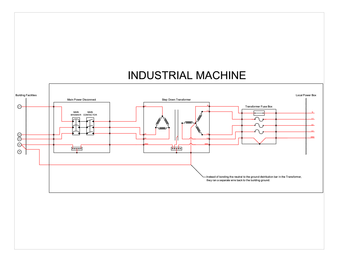
I am working on installing a large piece of industrial equipment in another country that doesn't necessarily hold the NEC as the electrical standard. This system has a transformer installed in the tool to drop the 415V factory power down to 208V. The transformer is a delta-wye isolation transformer.

The design that was proposed and initially built here in the States had the neutral of the secondary bonded directly to the ground distribution bar inside of the transformer. This ground was fed from the main feed ground through a power disconnect for the tool and also bonded to the frame of the tool.

When the tool was shipped and being installed. The electricians doing the installation disconnected my neutral to ground wire and ran a separate wire from the building ground to the neutral of the transformer. This really seems like a bad idea, I still have a path for fault current but its no longer reliable as I am trusting an external connection and have effectively increased the distance of the neutral bonding jumper.

I have tried to find some standards that other countries follow, but I can't even find an NEC standard that says what they did is wrong. It just doesn't seem safe to me.

The picture below shows the wiring as they currently have it.
NEUTRALBONDING.jpg
 

infinity

Moderator
Staff member
Location
New Jersey
Occupation
Journeyman Electrician
Can you re-post the diagram? It's too small to see the details and becomes too blurry when enlarged. From what I can see it looks correct.
 

bhulter

Member
New diagram. Woudn't it be more safe to bond neutral directly to ground at the transformer instead of running all the way back to the main feed?

POWERSYSTEMCONFIGURATION-WebPost.png


(Sorry about the huge pic)
 

infinity

Moderator
Staff member
Location
New Jersey
Occupation
Journeyman Electrician
IMO the graphic of the transformer is correct. The XO is bonded to the case and the GEC goes back to the main building ground. Am I seeing something that you're not? Also GEC would be required from the XO to be connected to the building grounding electrode system which is depicted by the line all the way back to the service.
 

Smart $

Esteemed Member
Location
Ohio
New diagram. Woudn't it be more safe to bond neutral directly to ground at the transformer instead of running all the way back to the main feed?

...
The diagram and your description do not match. The diagram shows a jumper from X0 to enclosure and a GEC (assumed) back to existing facility grounding system. Your description leaves out the bond at the enclosure.

Under NEC requirements the GEC is supposed to connect to the X0 terminal, but an exception allows the GEC to connect to the grounding bus. In either case, the system bonding jumper is to be connected from X0 to the grounding bus. In some cases, the enclosure serves as the bus... but when you actually have a grounding bus, that is where the connections are to be made. Even when the enclosure is used as the grounding bus, a diagram showing a separate grounding bus should only show one connection to the enclosure. In summary, the diagram is wrong.
 

Smart $

Esteemed Member
Location
Ohio
...diagram. ...
After looking at the diagram again, it appears that whoever drew it has designated terminations along the periphery of the "enclosure" rectangle. That in itself is enough to confuse anyone, knowledgeable or not. :happysad:
 

bhulter

Member
poor documentation

poor documentation

I apologize for the confusing diagram. I agree that I didn't do a very good job with the diagram, I whipped this up quickly and it is not clear.

The intent was to show bonding points with solid dots and a pass through as an unfilled circle. X0 is not bonded to the enclosure. That is not clear in the drawing.
 

jeremysterling

Senior Member
Location
Austin, TX
The description call the XFMR "isolation" and the drawing calls it "step-down." Sorry, couldn't resist.

I agree with the other replies: XO should be bonded to the ground bar in the XFMR as well as building steel. The first is your system bonding jumper and the second is your grounding electrode conductor. Both are required for separately derived systems.
 

kwired

Electron manager
Location
NE Nebraska
The question is whether this is common practice for European installations.

The OP clarified that it is not bonded to transformer frame until going back to the service first.

I see advantages and disadvantages both ways but don't know what European standards would be.
 

Smart $

Esteemed Member
Location
Ohio
The question is whether this is common practice for European installations.

The OP clarified that it is not bonded to transformer frame until going back to the service first.

I see advantages and disadvantages both ways but don't know what European standards would be.
What advantages?
 

Smart $

Esteemed Member
Location
Ohio
reduced possibility of neutral current on unintended paths, but it is countered by voltage drop.

selling more copper:)
A remote bond doesn't reduce the number of paths. It only changes the routing. The amount of neutral current on the grounding system may be lower due to increased resistance and thus voltage drop, but this will also be true for ground-fault current on the seconary side.

There is no change in the amount of copper, other than perhaps that of the system bonding jumper.
 
Last edited:

kwired

Electron manager
Location
NE Nebraska
A remote bond doesn't reduce the number of paths. It only changes the routing. The amount of neutral current on the grounding system may be lower due to increased resistance and thus voltage drop, but this will also be true for ground-fault current on the seconary side.

There is no change in the amount of copper, other than perhaps that of the system bonding jumper.

The drawing shows one conductor to the bonding point and one returning. That is not more copper than just one conductor?
 

bhulter

Member
Just got back!

Just got back!

Sorry this thread sat dormant for so long. I just got back from Malaysia where this installation was performed.

So, aside from the crappy documentation that I have provided here it looks like you guys are agreeing with me. X0 should be bonded to the ground distribution bar inside the XFMR.

My next step then is to find the proper documentation of a standard that I can use to convince the facilities guys over there to do it my way. Do any of you have experience working with IEC standards to know where I should be looking for this. I have done some searching and I am coming up with nothing specific enough to work in this application.
 

cadpoint

Senior Member
Location
Durham, NC
BH,

I hear it all the time from a friend who presents work for installations all the time.

What you present might not be what happens in the field!

Your Design is yours not the installers, what you present is your record copy and if your to chase the install, have them pay!
 
Status
Not open for further replies.
Top