240v debate....

Status
Not open for further replies.

__dan

Banned
Yes, that was my point. That's where the arguement is. Phase displacement is not true for the case of DC. Saying it is a polarity reversal is true for the AC and DC case.

The instantaneous flux in the iron core will have a net sum or aggregate value, magnitude and direction. For the case of the single iron core transformer with two windings, if the two windings have a similar load profile, instantaneous flux direction is the same for both load windings, winding turn direction is also polarized and matched by the manufacturer. Only under extreme, lab, conditions, like driving one load winding with an opposing current, could you maybe get different flux directions per winding simultaneous.

The reference point for the transformer is chosen by the manufacturer with essentially one secondary winding center tapped to offer a neutral, system grounding point. Winding turns continue in the same direction. The customer can choose to connect the load in a variety of ways.

Changing B, magnetic flux in the iron core, induces voltage in the secondary. Only by connecting the load, or the meter, in a reverse polarity config can the winding voltage appear to be out of phase. In fact they are, because the polarity of the connection is reversed.

Polarity in this case would refer to the winding turn direction, which are fixed and match. Of course the voltage is changing direction every 8.3 milliseconds.
 

jim dungar

Moderator
Staff member
Location
Wisconsin
Occupation
PE (Retired) - Power Systems
It is a simple fact that a two wire source has only one voltage but the three wire source has two voltages (three if we include the larger voltage). They are simply not the same. Anyone who has lost a neutral can tell you that.
And how do you suppose that losing a neutral is the same circuit that you had before? We have gone from a source with two smaller single-phase voltages and one larger single-phase voltage to a source with just one single-phasevoltage. Hardly the same at all.

Are you really saying the presence of an unused neutral point between two sources must always be considered, because it will provide different results than an equivalent 2-wire source? Or is it that different methodologies must be used because a neutral exits? If we can't get this multi-source issue resolved, how will we ever graduate to evaluating a circuit of two resistors in series (i.e. two 5' elements in a 10' baseboard heater) fed at 208V 2-wire from an open-wye source?
 

Rick Christopherson

Senior Member
Do you really understand flux or are you just throwing that out there because it "sounds" good? How do you propose that it is going to dictate the voltage direction? I'm open to studying any theory you might be proposing but I suspect you are mis-interpreting some of the known theory. Feel free to post the theory that shows the voltage directions must be the same as I do not recall the one you might be referencing.

The fact is, the flux does not determine the voltage direction because the choice of a voltage reference is just that: a choice.
Then you might want to start with Faraday's Law of Induction and Lenz's Law. They are the basis for how transformers function, and are the root to the simplified equations that we use day to day.

Faraday's Law:
The induced electromotive force (EMF) in any closed circuit is equal to the time rate of change of the magnetic flux through the circuit.

Lenz's Law:
An induced electromotive force (emf) always gives rise to a current whose magnetic field opposes the original change in magnetic flux.

Since the magnetic flux is originating from the single winding of the primary, then both secondary coils about the common core will have currents in the same direction, and that singular direction is the one that creates a magnetic field to oppose the original. In simpler words, the direction is not arbitrary nor dependent on any type of chosen reference point. It is dictated by the physics of electromagnetism. They're not guidelines. They're not hypotheses. They're not optional. They are physical laws.

Contrary to what you keep asserting, even though your choice of reference points may be arbitrary, once those two points are chosen, the voltage between them is not arbitrary. This goes back to my original battery example 3 years ago. You may chose to put your probes on the battery terminals in any direction, but doing so does not alter the chemical process that creates the voltage that you are reading. That voltage is fixed between those two points. The same is true for transformers, and Lenz's Law dictates the direction.

You can choose to solve your systems any way you wish, but that does not mean that you can redefine the systems as though your choice was absolute. As Jim and I have pointed out several times, you can't have a current direction that opposes the voltage (force) that created it. To do otherwise violates physical laws.
 

Rick Christopherson

Senior Member
Here's another diagram I found from the original discussion 3 1/2 years ago. (It's one I rescanned recently without realizing I already had one copy).

Question: Why is this diagram wrong?
Answer: Because instead of "examining" the voltage from n to b, the voltage has been redefined as though that examination was absolute.

This is what Mivey and Besoeker are doing when they claim that there is an absolute 180? phase difference between the two voltage sources, instead of simply that they have changed the polarity on their reference points.

The voltage source does not change. It remains the original 115@0?. The measurement of that source from n to b changes the observed polarity of the source, but it does not physically affect the source that is being observed.

3 1/2 years ago, I think I referred to this as the "voltmeter mentality". Instead of realizing that your voltmeter (scope) is simply changing your observation of a system, the Voltmeter Mentality tries to redefine the system based on the observation. You can change your observation of a system without violating the physical laws governing the system, but when you redefine the system based on your observations, then you end up in the situation I described in my previous post where you violate the physical laws governing the system.

3-wire-scan3.jpg
 

Besoeker

Senior Member
Location
UK
This is what Mivey and Besoeker are doing when they claim that there is an absolute 180? phase difference between the two voltage sources,
Nope.
The simple fact (yes, fact) is that, for the single phase centre-tapped transformer, Van and Vbn are mutually displaced by 180deg.
 

jumper

Senior Member
Gas grills don't do it for me. We do barbecue quite a bit, but use charcoal. Home made burgers at the weekend were well received.
If you want to use gas, you might just as well cook in the kitchen - we have a gas stove for that.

e_documents_and_settings_gunna_my_documents_my_pictures_broskarlar_36_1_72_562905.gif
 

Rick Christopherson

Senior Member
This is what Mivey and Besoeker are doing when they claim that there is an absolute 180? phase difference between the two voltage sources, instead of simply that they have changed the polarity on their reference points.
Nope.
The simple fact (yes, fact) is that, for the single phase centre-tapped transformer, Van and Vbn are mutually displaced by 180deg.
No? Really? Are you sure? You're not redefining the voltage source like I showed above?

Maybe you don't recall posting the following diagram that redefines the voltages as absolute regardless of the chosen reference points?

Not really.
Here's a simple diagram to illustrate the point I made about neutral current in post #49. It's one I've posted previously.

240Vsingle-phasebalanced.jpg


Unless the 120V supplies were in anti-phase i.e. 180deg apart, the neutral current would not, and could not, be not be zero.
For the sake of discussion, let's add labels to your nodes. Call the lower node "B", the middle node "N", and the upper node "A". You have labeled the voltages of your nodes: A=120v, N=0V, B=120V

As drawn, the voltage from N to A is 120V. The voltage from N to B is 120V. But OOPS, the voltage from B to N to A isn't 240V like you suggest. As Drawn the voltage from B to N to A is zero volts.

This isn't a one-time "oops, I messed up a single diagram". This is what you have been consistently arguing throughout this discussion. If you doubt that, the reason why I stumbled across this diagram again was because I was putting together a listing (a huge listing) of all of your posts where you keep restating this same type of information. You haven't been just talking about your reference to the voltage from N to B. You have physically redefined your voltage between those two nodes, and done so in a manner that violates Kirchhoff's Voltage Law (Kirchhoff's Second Law).

You are not simply saying that Van and Vbn are in opposition. That I would not disagree with. You are consistently redefining your sources in such a way that is contradictory.
 

pfalcon

Senior Member
Location
Indiana
Since energy can neither be created or destroyed, it was definitely converted to some other form of energy.
The energy is typically dispersed in the form of radiated heat.
Who knows? The Earth might have started spinning just a tad faster.
Nope, inertia again. Only mother-in-laws have that much mass.
If two balls of equal mass were positioned in deep, empty outer space within appreciable ranges of their space distortion, the gravitational forces will pull them together. Now who is to say which one moved in which direction? You have to define a reference frame and there is no "right" or "wrong" reference frame.
For this situation you've defined that there is no reference frame. Nor does gravity require one since it uses an absolute (always positive) value for separation. Therefore the question as to direction is based on false presumptions. There is no direction.

From my equation, Vab=Van-Vbn

240<0= 120<0 - 120<180... There you go, no double negative anywhere to be seen.

Of course you could force a double negative into the discussion of two 120V sources viewed from the perspective of having the same phase angle: Van=120<0 and Vnb=120<0.
Vba+Van+Vnb=0 :: Vba + 120<0 + 120<0 = 0
120<0 + 120<0 = -Vba :: 120<0 + 120<0 = -(-240<0) :: Vba=-240<0

120<0 - 120<180 does equal 240 but not <0. That statement would create a 240<0<180 load, dual-phased.
 
Last edited:

cowboyjwc

Moderator
Staff member
Location
Simi Valley, CA
John, ya gotta be more care careful when you build those things. I checked your math and you missed a negative, you are gonna wind getting eaten by a Morlock. Here try it this way next time:
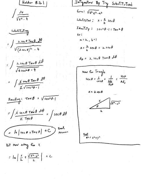
Trig-Substitution_1.jpg

See that's what I get for not checking my work. Guess that's way the furthest I could ever go was to the next day. And it took, like, 24 hours to get there.:dunce:
 
Status
Not open for further replies.
Top