7200 volt to 120/240 volt single phase transformer

Status
Not open for further replies.

mivey

Senior Member
Hello thought I would put my two cents in.

Every since I have been in the Electrical trade myself and other Electricians knew for a fact with
no doubt that in the Single Phase Electrical system feeding a house was just that single phase.
We are not debating that it is called single phase. That is what it is called. The term two-phase is reserved for a system in quadrature phase.

There is nothing out of Phase about it. It is only a polarity difference.Nothing is 180 degrees out.
Line one is line No. one and line two is line two and the center tap is a neutral between those two lines.

This misconception only started after the forums on the internet became popular.
Not true. This was understood long before the internet. I have reference books going back to the early 1900's that use that same terminology.

It has always been my opinion that all this stuff about referring too Line no. 1 as phase one and line no. two
phase 2 was brought about by the people posting here with a strong Electronic field. They are and have
always been taught when they reverse the polarity with a so called phase inverter they are shifting the
phase instead of the polarity. I don't think there is a thing wrong with calling this electronic stage a phase
inverter. But it just reverses the polarity also.
A center-tap transformer circuit has long been called a phase inverter.

Please in the Electrical trade lets not confuse Single Phase with 2 phase because of this belief.
As I said, two-phase is a reserved term. The issue comes down to definitions and there are too many standards out there that use them different ways that we will never reach a consensus on the use of the word "phase"

Electricians do not look at there voltages with oscilloscopes Electronic techs do.
Yes if you measure from the neutral two line 1 and neutral to line 2 it will appear as if you have two
sine waves 180 degrees out of phase with each other.
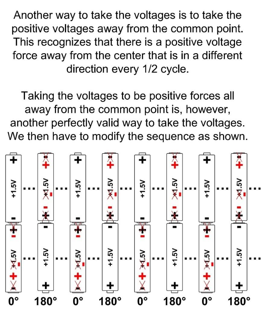
They just don't appear that way, they really are. The measuring device is not lying to you. It is just a load (but a very small load).

But if you use line one as the common when using a oscilloscope instead of the neutral you will
get two 120 volt sine waves in phase with each other and the polarities will also be the same.
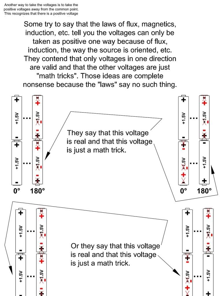
No, you will get one 120 volt wave and one 240 volt wave.

Using the neutral as common only makes it appear as you have two 180 degrees out of phase. The only
difference is the polarity they both rise and fall at the same time at the same rate.
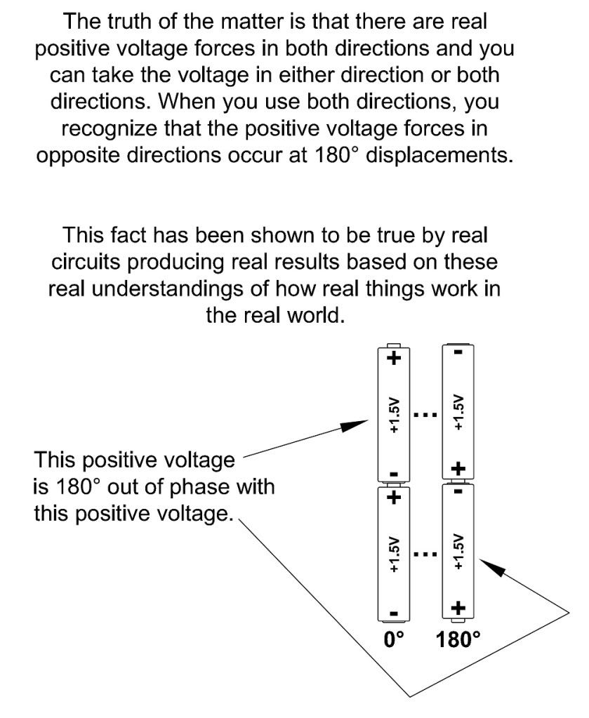
So do two waves produced by two generators that are physically displaced by 180?. See my post #98 here

Add: As well as the application of the two generators as a three-wire source in #290 here
 
Last edited:
Here are the corrected drawings:

BatterySeqTwoDir2.jpg


BatterySeqLaws2.jpg

Sorry but you can't use rotating angle representations with DC, just as you shouldn't use polarity with AC. An AC sinewave is 0 Voltage at 0, 160 and 360 degrees and maxes at 90 and 270 degrees.
 

Rick Christopherson

Senior Member
A 7200 volt to 120/240 volt single phase transformer has three terminals on the secondary consisting of line 1, neutral and line 2.
Is there two phases of 120 volts that oppose each other at 180 degrees or are the two 120 volt legs in phase with each other and in phase with the total 240 volt secondary?

Please explain your answer.
You have asked a very specific question with specific parameters. Your question also does not make any discussion about a common reference point. (By the way, if it was not fully pointed out previously, there is no need to have a common reference point. That is a personal preference.)

Given the way you have asked your question, the answer is that the two windings of the transformer are in-phase with each other. My reasons for stating that are the same as Jim's.
 

mivey

Senior Member
Sorry but you can't use rotating angle representations with DC, just as you shouldn't use polarity with AC. An AC sinewave is 0 Voltage at 0, 160 and 360 degrees and maxes at 90 and 270 degrees.
It was just an illustration to help Mike understand why the voltage difference from terminal b to terminal a is not zero but still 240 volts. I'm not a big fan of the battery comparison, but Mike seems to like it so I was trying to work with it.
 

Rick Christopherson

Senior Member
If you take end to end on the primary and end to end on the secondary, then yes, if you measure with respects to the starts and finishes, the dots, you will get two in-phase voltages.
If you measure the two hots with respect to the common centre point, usually taken as the neutral and commonly grounded in your part of the world, you will get voltages mutually displaced by 180deg.
Hey, guess what? We're in agreement on this. :roll:

I have never been able to find the math that shows how a single flux can create opposing voltages in a single conductor wound in a single direction.
I don't imagine that anyone with even the most basic knowledge of transformer theory would argue otherwise.
The three of us appear to be in agreement on this point too. Unfortunately, it would appear that someone else in this discussion is not on-board with this. :weeping:
 

mivey

Senior Member
The three of us appear to be in agreement on this point too. Unfortunately, it would appear that someone else in this discussion is not on-board with this. :weeping:
Then why don't you find out who that is and let us know?

I have never been able to find the math that shows how a single flux can create opposing voltages in a single conductor wound in a single direction.
Who said they did?
Are you saying the voltages in the two halves of a single winding are really in phase?
They are in phase if we are taking the voltages in the same direction.
 

Besoeker

Senior Member
Location
UK
Are you saying the voltages in the two halves of a single winding are really in phase?
Even though we can view/use them based on what we choose as a common point.
If you want a common point to measure the two 120V windings it has to be the centre tap. Use any other and you get two different voltages. Using the centre tap, call it neutral, then you get two voltages phase displaced by 180 degE.
 

Besoeker

Senior Member
Location
UK
But if you use line one as the common when using a oscilloscope instead of the neutral you will
get two 120 volt sine waves in phase with each other and the polarities will also be the same.
Not so.
If you use either line instead of neutral as the common for the measurements, you will get 120V for one of them and 240V as the other.
 

kwired

Electron manager
Location
NE Nebraska
Welcome to the reunion

Welcome to the reunion

unbelieveable, I think I will go argue about something with the dog:roll:
 

jwelectric

Senior Member
Location
North Carolina
Mike,

In the other thread you said


If you understand that the polarity is reversing, then perhaps we can use the battery analysis but with batteries that are reversing polarity every 1/120 of a second. Granted, the voltage won't be sinusoidal because the magnitudes are steady, but maybe it will be easier for you to understand what is being said.

BatterySeqTruth.jpg


I hope this clarifies what Besoeker, David, Laszlo, and I (I apologize if I forgot someone) have been saying. Whether or not you agree is up to you, but at least maybe you can stop mis-stating what we are saying.

This is not even close to what you are saying. The center tap on those batteries is half way between the two. Just replace the 1.5 volts with 120 volts on each battery to have what we are discussing. What you are showing is the full 240 (3) volt sine wave.

By the way what is the (+) and (-) in the center of each battery? Are you saying that the battery has a positive charge and then a negative charge?
 

mivey

Senior Member
This is not even close to what you are saying. The center tap on those batteries is half way between the two. Just replace the 1.5 volts with 120 volts on each battery to have what we are discussing. What you are showing is the full 240 (3) volt sine wave.
Yeah, the magnitude is the key to the whole thing.:roll: I get the feeling you just like to argue about most anything just for the sake of arguing. Besides, I was clean out of 120 volt batteries.

By the way what is the (+) and (-) in the center of each battery? Are you saying that the battery has a positive charge and then a negative charge?

I thought that would be easy for someone who claims:

jwelectric said:
I promise you that I have a full understanding of magnetic induction of a single phase transformer.

The signal alternates from positive to negative. An alternating current changes direction every 1/2 cycle. When you have an alternating wave, part is above the reference axis and part is below the reference axis (i.e. the "+" and "-" at the ends of the battery indicate the direction, the "+" and "-" at the voltage indicate when the wave is above or below the axis).
 

jwelectric

Senior Member
Location
North Carolina
Then what you are showing with the batteries is the full sine wave of 240 volts and you are not addressing the 120 volt aspect at all and it is the 120 volt that I have questions about.

No I am not just looking to argue just trying to reach a consensus as to the 120 volt sine wave. Are they or are they not in sync with each other. Do they or do they not oppose each other.

In order to address this issue with your drawing of the batteries the center tap of the transformer would have to relate to the midpoint between the two 1.5 volt batteries. What you are showing is the full sine wave of 240 (3) volts as it goes through one full cycle.

Now address the 120 volt and the center tap. If as you say the two 120 volt sine waves are 180 degrees out of phase with each other then one of the 1.5 volt batteries will need to be turned 180 degrees.

I have one secondary power source of 240 volts that has a center tap. Your batteries have a power source of 3 volts with a center tap. If as you say the two 120 volts are 180 degrees out of phase with each other then make the two 1.5 batteries be 180 degrees out of line with each other.
This is what I need to have addressed, please :)
 

Besoeker

Senior Member
Location
UK
No I am not just looking to argue just trying to reach a consensus as to the 120 volt sine wave. Are they or are they not in sync with each other.
Synchronised in that they both operate ate the exact same power frequency.

Do they or do they not oppose each other.
Opposed in that Van and Vbn are displaced by 180degE.

Now address the 120 volt and the center tap. If as you say the two 120 volt sine waves are 180 degrees out of phase with each other then one of the 1.5 volt batteries will need to be turned 180 degrees.
I'm not sure that batteries are the best analogy although Mivey did a fair job on that by showing a sequence over time.
Batteries have a steady state fixed voltage. Alternating voltage is a time varying quantity that goes through a cycle that sees a full range of voltages, both positive and negative, over that cycle. Assigning it/tem a polarity doesn't seem to be a very good way of showing that.


If as you say the two 120 volts are 180 degrees out of phase with each other then make the two 1.5 batteries be 180 degrees out of line with each other.
This is what I need to have addressed, please :)
Quite simply Van and Vbn are displaced by 180degE.
Note the order of the subscripts.
Note also that, if you want to have a common reference point and want to measure 120V from each end of the winding to that common point, you will get the voltages displaced by 180deg.
Two hots, one neutral.
 

Besoeker

Senior Member
Location
UK
By the way what is the (+) and (-) in the center of each battery? Are you saying that the battery has a positive charge and then a negative charge?
The diagram does not show that.
I think you missed the fact the battery stack has been physically reversed. Look at the drawing carefully. The positive remains the positive terminal on each cell.
 

jwelectric

Senior Member
Location
North Carolina
I'm not sure that batteries are the best analogy although Mivey did a fair job on that by showing a sequence over time.
Batteries have a steady state fixed voltage. Alternating voltage is a time varying quantity that goes through a cycle that sees a full range of voltages, both positive and negative, over that cycle. Assigning it/tem a polarity doesn't seem to be a very good way of showing that.
Yes I agree that batteries are not the same as AC but the principals of current flow is what I want to address. Take any of the two battery bank he posted and replace the 1.5 with 120 and we will have what needs to be addressed. You and him say that reading the voltage from either line to the center tap shows an opposing cvoltage that is 180 degrees out with each other and this would add up to be 240 volts. Using the same math add the two batteries by adding the 1.5 volts together to get 3 volts. Once we have added them together to get 3 volts do the reading from one end to the center and the other end to the center and see if the polarities of the two are opposing each other at 180 degrees.
If it won?t work with DC then it won?t work with AC either.


Quite simply Van and Vbn are displaced by 180degE.
Note the order of the subscripts.
Note also that, if you want to have a common reference point and want to measure 120V from each end of the winding to that common point, you will get the voltages displaced by 180deg.
Two hots, one neutral.
What I will see on the scope is two voltages that are displaced by 180 degrees but this is simply because of the way the scope is connected. Just as with traffic and standing on the side of the road looking into the center of the road I see traffic moving from my left to my right Van. Now cross the road and look at traffic from the other side and it is still moving from my left to my right Vbn. Low and behold they are going the same way when I stand on the outside and look inward just as the scope you have connected is doing.

I can see no way that a single core transformer can displace the magnetic flux of the secondary in two different directions that are separated by 180 degrees.
As with the two 1.5 batteries should they oppose each other by 180 degrees they would simply cancel each other out and there would be no voltage reading across the total bank at all. Is this not simple vector addition?
 

Besoeker

Senior Member
Location
UK
What I will see on the scope is two voltages that are displaced by 180 degrees but this is simply because of the way the scope is connected.
Yes. If you want to see how the two 120 voltages Van and Vbn are related in time wrt a common point the N centre tap is the only choice for that common point. Any other won't give you two 120s. Two hots, one neutral.


I can see no way that a single core transformer can displace the magnetic flux of the secondary in two different directions that are separated by 180 degrees
I don't imagine that anyone with even the most basic knowledge of transformer theory would argue otherwise. See post #7
 
Status
Not open for further replies.
Top