Joethemechanic
Senior Member
- Location
- Hazleton Pa
- Occupation
- Electro-Mechanical Technician. Industrial machinery
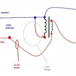
I had this idea, but I'm thinking it might be a problem. This is for a piece of test equipment. 120V in with a 32 volt boost.
The reason I wanted to put the switch there is because it is a low current portion of the circuit
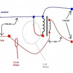
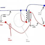
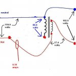
What I'm worried about is , it the switch is thrown under load, the primary windings could end up with a voltage of almost 4 times the 120 volt line imposed on them. Possibly damaging the transformer and requiring a 480 V rated switch.
Do you think I'm worrying needlessly?
And this was the original question. I already scrapped the idea of a switch on the primary side almost a day ago. I just wanted to see who was on the ball,,,,,,,,,,,,,,,