Why is residential wiring known as single phase?

Status
Not open for further replies.

Rick Christopherson

Senior Member
Why do you keep ignoring what is being said, and keep focusing on what isn't being said? The contention is your "absolute" wording. Do you not understand what that means?
 

jim dungar

Moderator
Staff member
Location
Wisconsin
Occupation
PE (Retired) - Power Systems
Sure, you can have things connected end to end as well as either end to neutral.
The end to end load would be connected between two hots. Why would it be reasonable to designate one particular hot as a common reference? Common to what?
The only common connection between the two loads is a hot, why wouldn't you use it as a reference?

this forum has seen many troubleshooting issues where the poster just used N or G as a voltage reference, only to find out the reference was actually not part of the circuit, like with a floating neutral or an ungrounded system. Eventually the real problem was diagnosed by using multiple references and comparing the expected values.


My reference was to 120-0-120. But the comments would be equally applicable to 180-0-60.
But again you are thinking of the neutral as the only point of reference. Have you ever worked with the 60/120V circuits used in recording studios? How about multi-tapped control power transformers with both 24V and 120V outputs?


First part:
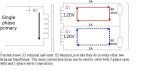
I don't suppose that you would argue with the point that a transformer wound to give 120-0-120 even if it is two isolated windings connected in series will give 240V end to end.

Second part:
Suppose you load the two 120V supplies, one with a 40 ohm resistor, the other with 60 ohms.

This cancelling of the currents in the neutral is one of the merits of a 120-0-120 system

Why does it happen?

It happens because the two load currents oppose each other, not because the voltages do.
 

Attachments

  • single-phase.JPG
    single-phase.JPG
    60.6 KB · Views: 0
Last edited:

Rick Christopherson

Senior Member
is what you posted.
So post what you think is a correctly labeled diagram.
Can you not get it through your thick head that I don't have problem with your diagram. There is nothing wrong with an unlabeled diagram. It is your absolute statements made against an unlabeled diagram that is wrong. Even making absolute statements against a fully labeled diagram is questionable, but is at least somewhat defendable.

You're so headstrong in trying to force the world to analyze a system using your analysis method that you can't comprehend the difference between analysis tools and defining the system. Analyze the system whatever way you want, but quit defining the system based on your chosen analysis tools.
 

Besoeker

Senior Member
Location
UK
But again you are thinking of the neutral as the only point of reference.
No. Just as the most logical since it is the only single common point.
Have you ever worked with the 60/120V circuits used in recording studios? How about multi-tapped control power transformers with both 24V and 120V outputs?
Recording studios, no.
But multi-tapped transformers, yes. Including some at upwards of 100MVA.

It happens because the two load currents oppose each other, not because the voltages do.
For the resistive loads I gave, the voltages and currents are in phase for each half of the circuit. Restive loads do that.
The current in the neutral cancels because of the 180deg displacement.
 

Besoeker

Senior Member
Location
UK
Can you not get it through your thick head that I don't have problem with your diagram. There is nothing wrong with an unlabeled diagram. It is your absolute statements made against an unlabeled diagram that is wrong.
Fine.
Cite any absolute statement I made that is absolutely wrong.
Be succinct and direct.
 

jim dungar

Moderator
Staff member
Location
Wisconsin
Occupation
PE (Retired) - Power Systems
But multi-tapped transformers, yes.
Did they have common points that were not neutrals?

For the resistive loads I gave, the voltages and currents are in phase for each half of the circuit. Restive loads do that.
The current in the neutral cancels because of the 180deg displacement.
But, based on the notations I placed on your diagram, the voltages do not have a 180? shift, they are additive (Vbn ->Vna), and yet the currents still cancel.
No double negatives were required.
The physics of the transformer were considered.
Resistive currents are in-phase with the voltages.
Each node has currents that enter and leave.

One diagram, two logical interpretations.
So, other than the placement of your scope leads, where is the proof that a real shift occurs?
 

Rick Christopherson

Senior Member
Fine.
Cite any absolute statement I made that is absolutely wrong.
Be succinct and direct.
I did quote you, and I did state what was wrong when this topic came up earlier today. Either it is not sinking in or you are being deliberately obtuse and/or deceptive.

It is well known that I do not have the patience for stupid people, and I make no apologies for that. I don't know if you are one, but right now you are presenting yourself as one. If you are not competent enough to comprehend the discussion you are engaging in, then it is probably best to ignore you again.
 

jim dungar

Moderator
Staff member
Location
Wisconsin
Occupation
PE (Retired) - Power Systems
Oxymoron comes to mind.
Does the range example I have often cited, have a common conductor between the two loads? Is it the neutral of the voltages?

I employed none.
Other than to say Vbn = -Vnb?
Actually I was trying to address the points I raised in a previous postings.

Although now that you bring it up. You posted a nice graph and current values for a 3-load circuit. I don't think I saw your 2-load results? David and I discussed his results, which brought up the issue of a node with two currents entering but none leaving.

That there are a huge number of circuits in operation that work as a result of that 180deg displacement.
Hundreds, going on thousands, of posts and I have yet to see a single one saying these circuits, like the rectifiers you are rightly proud of, cannot work. I said there appears to be a displacement based on the way you choose to reference your wiring (not the actual wiring itself). Choose a different reference and there appears to be no displacement. Are you saying my notations, showing 0? displacment, on your diagram, are incorrect?
 

rattus

Senior Member
Trivia:

Trivia:

I am not contesting your assumption. I am contesting your absolute statement. Don't state absolutes if they have conditions. It wasn't simply a matter that you "lightly misspoke". You emphatically stated it as an unequivocal absolute.

When discussing phase shifts, one knows or should know that only the fundamental frequency carries a phase shift. One should also know that dwelling on such minutiae does not add any value to the discussion.
 

rattus

Senior Member
120205-1133 EST

Does a transistor or triode vacuum tube produce a 180 deg phase shift of a sine wave input? With what connection of input and output does this shift occur or not occur?

.

Yes it does. One can however add an emitter resistor or cathode resistor to obtain 0 and 180 degrees.
 

gar

Senior Member
Location
Ann Arbor, Michigan
Occupation
EE
120205-1949 EST

rattus:

Right on. Can the orhers see it? From the earliest days of a triode oscillator there had to be the realization of the phase shift between the grid and plate of the triode.

.
 

jumper

Senior Member
I did quote you, and I did state what was wrong when this topic came up earlier today. Either it is not sinking in or you are being deliberately obtuse and/or deceptive.

It is well known that I do not have the patience for stupid people, and I make no apologies for that. I don't know if you are one, but right now you are presenting yourself as one. If you are not competent enough to comprehend the discussion you are engaging in, then it is probably best to ignore you again.

Insults and disparaging remarks are a sign of a desperate man......:roll:

Bes' challenge is to post math and diagrams, well.......
 

jim dungar

Moderator
Staff member
Location
Wisconsin
Occupation
PE (Retired) - Power Systems
Right on. Can the orhers see it? From the earliest days of a triode oscillator there had to be the realization of the phase shift between the grid and plate of the triode.

Different argument/discussion. Can you show where someone has said that a shift is always impossible?

Besoeker posted a diagram without notations and said it 'showed' a shift. I added notations to that diagram that showed there is no phase shift. I included logical reasons to use my method which refuted issues I had noted.
 

__dan

Banned
Insults and disparaging remarks are a sign of a desperate man......:roll:

Bes' challenge is to post math and diagrams, well.......

Calling the man desperate for charging the phase shift arguement with deception, obfuscation is an ad hominem attack.

Look at the truth. How many in the audience are only more confused by being told "there is a phase shift". It's like being told "it's by smoke and mirrors" to which more of the audience will say " ah ha". It's the eureka effect, the discovery of useful knowledge. For most of the audience being told there is a phase shift will sound like something to be afraid of, something bad, something that may be exceptionally difficult to understand

The reality is that reversing the polarity of the load relative to the winding turn direction causes an artifact that can be measured or described as a 180 deg phase shift. The phase shift arises from the polarity reversal relative to the load and is a special case. The phase shift is not native to the operation of the subject single phase transformer, which is what the audience is afraid of or confused about. Saying yes there is a phase shift happening does nothing to relieve this confusion.

And a source of confusion it is, since the transformer with no external conection offers two indentical, matched, "in phase" windings that can be connected in a variety of ways. If the electrician knows how the artifact of a phase shift occurs, by reversing the polarity of the load relative to the winding turn direction, he has a better chance of understanding the physical reality of why the wires are bolted here or there.

The paradigm is for the mental comfort of the concerned person. Is this right or will it go poof.

Notice that the same thing happens with two batteries in series, which is an appeal to logic, a broad, true, and useful description. The usefulness of the description makes it science. If the description does not convey understanding, it fails the test of usefulness.
 

Rick Christopherson

Senior Member
Insults and disparaging remarks are a sign of a desperate man......:roll:

Bes' challenge is to post math and diagrams, well.......

Calling the man desperate for charging the phase shift arguement with deception, obfuscation is an ad hominem attack.
Not only that, but he "Jumpered" to conclusions without actually reading what I wrote. There were no disparaging remarks in what I wrote. He assumed that there were because he didn't read it carefully. I write for a living. I choose my words carefully.
 

ronaldrc

Senior Member
Location
Tennessee
Here we go again, trying to apply electronics to prove this point again.

I said this 5 years ago and I'll say it again it is the people with a strong education in electronics causing this
confusion about single Phase power being two phase. This was never a problem before the internet became
popular and Electronic techs. and Electricians started talking together about it.

I studied Electronics also 40 plus years ago. I have for gotten most of it.

But I do remember studying phase inverters for Class C or push pull Amplifiers.

And if you Techs are honest enough and are willing to eat some crow you would admit that the so called
Phase inverter rather it be a transformer with a center tap or amplifier element such as a triode vacuum tube
or a transistor, it does no more than invert the input signal or reverses its polarity.

The output of the so called phase inverter in a audio amplifier does not shift the phase it reverses the polarity.
There is no phase shift it is inverted.

I realize you where and are being taught this.But it is a polarity inverter ,but please give it some serious thought.

And have enough nerve to admit single phase is just that ?single phase?. :)
 

Besoeker

Senior Member
Location
UK
Can you not get it through your thick head that I don't have problem with your diagram.
As ever, you exude charm.
My diagrams and words are examples of what I do in my day job.
Design, manufacture, test, ship, commission, and support.
Stuff like this:

C12273-twoLHSlimbs02.jpg


Getting the design or calculations wrong isn't an option. And being thick wouldn't excuse it. But hey ho.....on we go.
And you?

I'm also a moderately practical fellow.

This:

Junebatch07027.jpg


To this:

Julybatch08042.jpg


in a weekend. Including the painting, the laminate floor, a new commode (not shown), the plumbing for it etc. The taps and waste for the basin were done the following weekend.

Simple point. I don't do just theory.
 
Status
Not open for further replies.
Top