Why is residential wiring known as single phase?

Status
Not open for further replies.

jim dungar

Moderator
Staff member
Location
Wisconsin
Occupation
PE (Retired) - Power Systems
No, a reference is a node
Please quote a source of this absurde claim.

As my reference for a current and thus a voltage direction, I choose the H1 and X1 relationship established by the manufacturer of the transformer following IEEE/ANSI standards.

I am beginning to wonder if you have ever solved a network that did not have neutral point?


Let me say this, the practice of using the neutral as a reference and saying that the voltages seen on L1 and L2 are out of phase by PI is well established.
Yes it is a common practice, in fact if you bothered to actually read my postings, you would have seen where I said that on occasion I follow this practice. Just like calling a conductor a phase is also a common practice, which I am sure you follow. Saying we have a negative potential difference (i.e. voltage) between two terminals is also a common practice.

A practice is not a requirement it is simply an arbitrary choice. Not acknowledging the underlying facts of the common practice is a poor practice.
When you say you have identical windings (i.e. a center-tapped winding), you are establishing a physical fact. You are free to use the individual voltages any way you want, but as soon as you combine them, you need to remember they started out and therefore must eventually finish as being identical.
 

rattus

Senior Member
As you say, inversion and phase shift are not the same thing. Phase shift is a function of time delay. This is a common error in audio terminology; folks often talk of signals being "out of phase" when they really mean "reverse polarity". In waveforms more complex than pure sine waves they are not even remotely the same.

But this is not audio. We are talking ideal sinusoids. True, there is no time delay as in amplifiers or delay lines, but the term 'phase shift' is widely accepted in the power industry. Matter of fact, it could be a phase lead or lag. The phase has shifted for whatever reason.
 

rattus

Senior Member
Please quote a source of this absurde claim.

As my reference for a current and thus a voltage direction, I choose the H1 and X1 relationship established by the manufacturer of the transformer following IEEE/ANSI standards.

I am beginning to wonder if you have ever solved a network that did not have neutral point?


Yes it is a common practice, in fact if you bothered to actually read my postings, you would have seen where I said that on occasion I follow this practice. Just like calling a conductor a phase is also a common practice, which I am sure you follow. Saying we have a negative potential difference (i.e. voltage) between two terminals is also a common practice.

A practice is not a requirement it is simply an arbitrary choice. Not acknowledging the underlying facts of the common practice is a poor practice.
When you say you have identical windings (i.e. a center-tapped winding), you are establishing a physical fact. You are free to use the individual voltages any way you want, but as soon as you combine them, you need to remember they started out and therefore must eventually finish as being identical.

How can one reference a voltage to the X1/H1 relationship? That just doesn't make sense. Where does one place the probes? Am I supposed to place my probe on the polarity dot?

A reference (written) which defines a node (electrical) as a reference (electrical) perhaps exists, but most of us don't need one.
 

ggunn

PE (Electrical), NABCEP certified
Location
Austin, TX, USA
Occupation
Consulting Electrical Engineer - Photovoltaic Systems
No, not really. It would be helpful though if you would state your opinion on the following bones of contention:
Well, OK.

An inversion produces a PI radian phase shift.
Disagree. A phase shift is an operation in the time domain and an inversion is not. The fact that for a sine wave an inversion looks the same as would a 180 degree (pi radian) phase shift is a coincidence, a special case for a pure frequency and a particular delta tee. A phase shift is made by displacing a waveform horizontally along the time axis and an inversion is made by reflecting the waveform vertically about that axis.

A center tapped transformer splits the single phase of a residential system into two voltages with two phase angles, therefore two phases.
Disagree. All a center tap does is provide a different reference point for observing the same single phase waveform.

A sine wave cannot carry the same phase as its inverse. Neither can it be in phase with its inverse.
A sine wave and its inverse do not differ from each other in terms of phase, but in polarity. IMO this is a non sequitur.

Signs do matter with trig identities.
In what context? In terms of pure mathematics, of course they do.

The use of the neutral as a reference point is widely accepted.
Accepted for what?
 
Last edited:

rattus

Senior Member
ggunn


Join Date
Oct 2009
Location
Austin, TX, USA


Originally Posted by rattus
An inversion produces a PI radian phase shift.

Disagree. A phase shift is an operation in the time domain and an inversion is not. The fact that for a sine wave an inversion looks the same as would a 180 degree (pi radian) phase shift is a coincidence, a special case for a pure frequency and a particular delta tee. A phase shift is made by displacing a waveform horizontally along the time axis and an inversion is made by reflecting the waveform vertically about that axis.

Fine points noted, but for all practical purposes, for infinitely long sinusoids, they are the same and the term is widely used in the power industry. You can't tell the difference.

Originally Posted by rattus

A center tapped transformer splits the single phase of a residential system into two voltages with two phase angles, therefore two phases.

Disagree. All a center tap does is provide a different reference point for observing the same single phase waveform.

But when we do that, we see waveforms with phase differences.

Originally Posted by rattus View Post

A sine wave cannot carry the same phase as its inverse. Neither can it be in phase with its inverse.

A sine wave and its inverse do not differ from each other in terms of phase, but in polarity. IMO this is a non sequitur.

But they carry different phase angles e.g., 0 and PI. If they are of the same phase one could short them together with no sparks.

Originally Posted by rattus

Signs do matter with trig identities.
In what context? In terms of pure mathematics, of course they do.

Specifically the claim was made that the phase of [-sin(wt)] = wt, but when expanded to sin(wt + PI) the phase is wt + PI.

Quote Originally Posted by rattus
The use of the neutral as a reference point is widely accepted.

Accepted for what?

As a reference node for the voltages on L1 and L2.
 

ggunn

PE (Electrical), NABCEP certified
Location
Austin, TX, USA
Occupation
Consulting Electrical Engineer - Photovoltaic Systems
ggunn


Join Date
Oct 2009
Location
Austin, TX, USA


Originally Posted by rattus
An inversion produces a PI radian phase shift.

Disagree. A phase shift is an operation in the time domain and an inversion is not. The fact that for a sine wave an inversion looks the same as would a 180 degree (pi radian) phase shift is a coincidence, a special case for a pure frequency and a particular delta tee. A phase shift is made by displacing a waveform horizontally along the time axis and an inversion is made by reflecting the waveform vertically about that axis.

Fine points noted, but for all practical purposes, for infinitely long sinusoids, they are the same and the term is widely used in the power industry. You can't tell the difference.

Just because you cannot tell the difference, that doesn't mean they are the same thing. If it were a phase shift, then differing degrees of it would yield different phase relationships. In this case, differing degrees of the effect yield changes in magnitude.

Originally Posted by rattus

A center tapped transformer splits the single phase of a residential system into two voltages with two phase angles, therefore two phases.

Disagree. All a center tap does is provide a different reference point for observing the same single phase waveform.

But when we do that, we see waveforms with phase differences. They aren't changes in phase, they are changes in magnitude, passing through zero and becoming inverted.

Look, you can obviously argue about this until we are all blue in the face, but it's really a question of relativity. What you see depends on where you are observing it from.

But consider this: In our example of our transformer with the center tapped secondary, if there were a very narrow transient voltage spike on the primary and you were monitoring both the voltage on A and the voltage on B with N as a reference, you would see the spike simultaneously on both A and B. If B were phase shifted from A you would see the spike at different times on A and B.

But all this is really BS. We all agree what the waveforms look like; this furor is all over what we call it. Call it Englebert Humperdinck for all I care; it's just semantics.
 

jim dungar

Moderator
Staff member
Location
Wisconsin
Occupation
PE (Retired) - Power Systems
How can one reference a voltage to the X1/H1 relationship? That just doesn't make sense. Where does one place the probes? Am I supposed to place my probe on the polarity dot?

A reference (written) which defines a node (electrical) as a reference (electrical) perhaps exists, but most of us don't need one.

X1 is an identifiable terminal on a transformer winding. You can place a probe on this terminal. I am surprised you did not know this.

You can make the arbitrary choice of calling the X1 terminal the 'tail' of your phasor, with the 'head' of the phasor pointing towards the other terminal. After all your talk of using phasors, I would have thought you would have known of this methodology, maybe you do need a written reference describing this procedure?
 

mivey

Senior Member
The discussion is very much relevant to the topic. The question is "why is this called single phase", and the answer is because there is only one physical phase angle.

There is only one physical phase angle present for a two-wire source. It is called single-phase because the larger voltage is a two-wire source. One voltage, one phase.

The apparent phase shift is mathematical, not physical. So there is only one. So whether you want to deny it or not, this is very much relevant to the topic.

Again, the phase shifts we have with taking transformer voltages from different terminals and in different winding directions do not require a time shift.


My argument has been with those individuals that are falsely trying to bolster their position by stating that a real and/or physical phase shift exists that they have emphatically claimed was not just mathematical.

As for real: The phase shifts by inversion are just as real as the other transformer phase shifts. There is no difference from the delta-wye 30? or 210? shifts because they are not time shifts either. Same for the shift from the Scott, open-wye to 4-wire wye, and other connections.

For me to go along with your terminology, you would also have to denounce the other transformer shifts as being real phase shifts. In the past you have stated they were real shifts. I will never agree with you on that basis because it is not consistent.

The transformer phase shifts/displacements/differences are widely recognized and called to be phase shifts and that is not going to change: that ship has sailed. However, for the purposes of using common terminology between you and I, if you will stipulate that the other transformer shifts are not real shifts either, then I can accept that terminology agreement between us and sail in the same ship with you.

However, do not expect me to stick to that terminology outside of that ship because it is common industry terminology to call non-time shifts in transformers and other circuits by the term "phase shifts".
 

mivey

Senior Member
Discussing the phase relationship between Vbn and -Vnb, which seems to be Rattus' focus, involves a single waveform.
I'm pretty sure he was discussing it in relation to ultimately using the result along with the Van or Vna voltage. I'm pretty sure he has already stated and knows that with one two-wire voltage you can only have one phase present.

A transformer physically wired Vx1x2 connected to Vx3x4 produces a single waveform Vx1x4. This is the reality of the winding interconnections.
That is correct. Vx1x4 is a larger, single voltage but as C.P. Steinmetz recognized, it does not mean the two smaller voltages are not present and that is also a reality of the center-tap transformer winding connections.

How you manipulate, fondle, measure, use, or abuse the individual voltages of Vx1x2 and Vx3x4 is strictly arbitrary, but none of that changes the actual result of a single voltage, Vx1x4, with a single waveform.
Nor does the presense of the larger Vx1x4 voltage mean that the two smaller voltages have disappeared. We can use these smaller voltages to produce constructive or destructive interference.
 

mivey

Senior Member
I do not believe that anyone is arguing that it is not a "single phase" service from the perspective of a useful name. Admittedly the original question was "why is residential wiring known as single phase", and there has been very little real discussion on that aspect.
My statement was that you have a larger single-phase voltage and that is the reason it is called single-phase. But as C.P. Steinmetz noted, the system of two smaller phases were still present as well. As for the smaller opposed phases, he said that if we consider one to be the return of the other, we get the resultant larger single phase.

Let it go on the record, Gar says there is a potential difference (voltage) between the two ends of a length of wire in an alternating magnetic field.
So let it be written. So let it be done. {Trumpets} :D
 

mivey

Senior Member
It's all still single phase because all you are doing is looking at the same single phase waveform from different reference points.

Is it really any more complicated than that? I'll hang up and listen...
The larger voltage is a two-wire source and you will only have a single phase present in a two-wire circuit. Also, the smaller voltages we take are normally used as two-wire sources. That is why we call the combined system of voltages we take from the transformer a single-phase system.

However, we also have a system of two smaller voltages that can be used to produce constructive or destructive interference. Thus, we can have two smaller voltages in phase or two smaller voltages in phase opposition. It is just that simple.
 

mivey

Senior Member
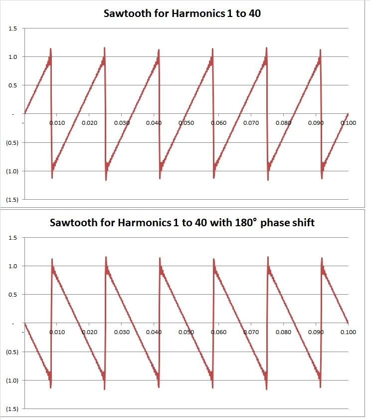
Something you might want to discuss relative to phase shift and inversion is what happens if the excitation is a sawtooth. Meaning it starts at -V, goes thru 0 at PI (0.5 period), and to +V at 2*Pi (one period).
Same topic as the noise example I gave in #1778: the phase shift in the transformer is not a time shift.

There is no phase shift that produces a result equivalent to an inversion.
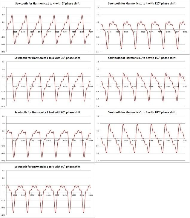
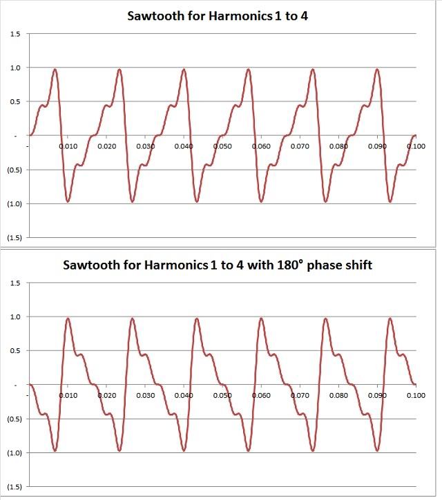
Yes, there is. What you have with the sawtooth is a piece-wise function, or a bucket full of wave harmonics. If we shift each harmonic wave by 180?, you have the equivalent inversion. You can't find one time shift that covers multiple frequencies because the domains don't mesh like that.
 

mivey

Senior Member
As you say, inversion and phase shift are not the same thing. Phase shift is a function of time delay.
Only in the terminology of some specific fields. Phase shift does not always have to be a function of time delay. The terminology varies. In addition to power transformer terminology, look at baluns and phase splitters.

This is a common error in audio terminology; folks often talk of signals being "out of phase" when they really mean "reverse polarity". In waveforms more complex than pure sine waves they are not even remotely the same.
Not an error. Just a difference in terminology. Phase shift is also defined as the displacement between similar points on waves. There is not one universal definition.
 

mivey

Senior Member
There is no phase shift that produces a result equivalent to an inversion.
Yes, there is. What you have with the sawtooth is a piece-wise function, or a bucket full of wave harmonics. If we shift each harmonic wave by 180?, you have the equivalent inversion. You can't find one time shift that covers multiple frequencies because the domains don't mesh like that.
Here are some examples.

For the first four harmonics:

H4Sawtooth.jpg


Now increase the number of harmonics included by a factor of 10:

H40Sawtooth.jpg
 

gar

Senior Member
Location
Ann Arbor, Michigan
Occupation
EE
120317-0800 EST

mivey:

When a waveform is disassembled into its individual components and a 180 degree phase shift is individually applied to each component, then the result is as you show. That is what the transformer does.

When the phase shift is applied to the whole waveform as in a time shift (propagation thru a long cable) or in differential paths thru space as in acoustic or light waves, then the waveform does not see an inversion.

When a pulse of white light is sent thru space and we look at it at another point, it is still a pulse of white light, but phase shifted or time delayed.

When white light is applied to two or more uniformly spaced slits, and then we view the light at some angled points beyond the slits, then we see different colors at different points because of the different phase shifts vs frequency (wavelength).

I have no conflict with any of these effects. They all have to be viewed from the conditions under which they are studied.

.
 

jim dungar

Moderator
Staff member
Location
Wisconsin
Occupation
PE (Retired) - Power Systems
....it does not mean the two smaller voltages are not present and that is also a reality of the center-tap transformer winding connections.

I have not, nor have any others, claimed a voltage does not exist. In the post you quoted, I specifically said these voltages may be used. To make this inference in a reply directed specifically to me is a demonstration of the steps you take to obfuscate the discussion.
 

jim dungar

Moderator
Staff member
Location
Wisconsin
Occupation
PE (Retired) - Power Systems
Here is a progression for the first 4 harmonics from 0? to 180? shifts.

Obfuscation at its best. Again you post examples that have nothing to do with the core discussion, and are not usually even points of contention.

Most of the participants have been trying to focus this discussion to the sinusoidal waveform(s) associated with 120/240V single phase, and particularly the inversion or shift of Vbn based simply on a reference point change.
 

rattus

Senior Member
X1 is an identifiable terminal on a transformer winding. You can place a probe on this terminal. I am surprised you did not know this.

But you said H1/X1 relationship which is not a node at all. Yes, X1 equates to L1 perhaps, or maybe it is L2.

You can make the arbitrary choice of calling the X1 terminal the 'tail' of your phasor, with the 'head' of the phasor pointing towards the other terminal. After all your talk of using phasors, I would have thought you would have known of this methodology, maybe you do need a written reference describing this procedure?

Yes, I could do that, but I prefer to place the tail of the phasor on N, just like is done with the wye. The value of the phasor is then the value of that 'phase' with the wye or the split phase system. Of course, if there is no neutral, one cannot do that.

Never saw a wye phasor diagram with the arrows pointing toward the neutral.

Now, are you still claiming a sine wave and its inverse are of the same phase??
 
Status
Not open for further replies.
Top