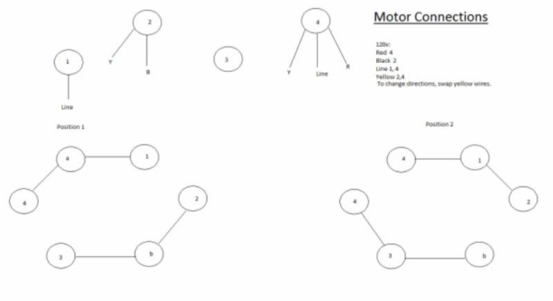
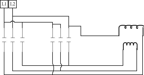
So there's this vertical milling machine that someone decided to tear apart and now I get to clean up the mess. Most of my experience is with lighting and simple branch circuits, so motor control is new to me. I sat and stared at it for a while, but I'm having a difficult time understanding how to swap the starter leads without putting a line wire where it doesn't belong. I drew up this picture to show you my dilemma. The bottom is the 6 connector switch and it's two positions. The third position breaks all connections. Sorry for the lacking paint skills.