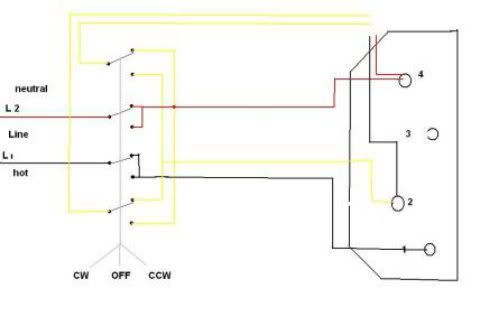
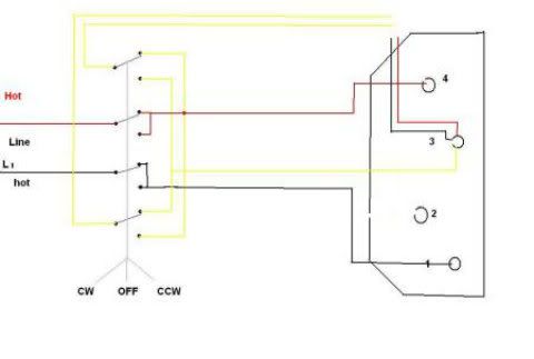
What Am I Missing? (Motor Reversing)

Status
Not open for further replies.

Smart $

Esteemed Member
Location
Ohio
Correct, I wish to reverse the motor via the reversing switch that was mounted to the machine, wires all in disarray. The lower half of my drawing represents the switch positions, the lines between the circles represent continuity between connectors, and the letters are exactly as written on the actual switch. I understand the yellow wires at the motor will have go through the switch. And yes, the switch makes no contacts in the off position. I'm not familiar with CCW and CW, but the switch is labeled forward and reverse for it's two running positions, off being the center position.
What I gather so far...

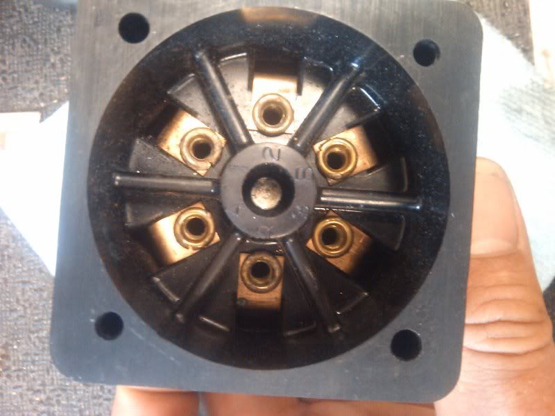
Motor terminal 1 (will abbreviate as M# hereafter) backside is one end of the overload. The other end of the overload is M2 backside. Also backside, one end of main winding 1 is connected to M2, while the other end is the Red lead. One end of main winding 2 is connected backside of M4, while the other end is the Black lead. M3 has no backside connections.

Yellow leads are lifted and must be connected to switch terminals 2 and 4 (S# hereafter). Their complements going back to the motor connect to Sa or S1 and Sb or S3, then to M2 and M4 respectively.

As the overload is assumed to be between M1 and M2 and M2 is also connected to one end of one main winding, I can't think of way to swap yellows and also disconnect both lines right now... so let's say Neutral line is connected to M1. The Hot line could connect to Sa, Sb, S1, or S3, whichever is the mate for the complement wire connected to M4. That is, for example, if the complement wire connected to M4 is connected to Sa, then connect Hot to S1.

Thoughts?
 
Last edited:

kwired

Electron manager
Location
NE Nebraska
Correct, I wish to reverse the motor via the reversing switch that was mounted to the machine, wires all in disarray. The lower half of my drawing represents the switch positions, the lines between the circles represent continuity between connectors, and the letters are exactly as written on the actual switch. I understand the yellow wires at the motor will have go through the switch. And yes, the switch makes no contacts in the off position. I'm not familiar with CCW and CW, but the switch is labeled forward and reverse for it's two running positions, off being the center position.

The switch is probably what many call a drum switch. One of the poles will make straight through in forward or reverse, the other two will reverse polarity in reverse than they have in forward. Off position (all three poles open) is likely center position.

Figure out which pole is straight through and then look at diagram I submitted earlier. My diagram shows contactors but the circuit is still same contacts are just operated by different mechanism.
 

Smart $

Esteemed Member
Location
Ohio
Here's my stab at it- Top diagram from the OP shows the motor hooked up for 120V so, 2 and 4 on the switch are starting and go where the motor diagram shows yellow wires, 1 and 3 go one and four on the motor and power goes to A and B.
Connected as you suggest, if the overload is connected internally between motor one and two (going with your formatting), wouldn't that leave power connected to the start winding (yellow wires) when the overload trips?
 

hurk27

Senior Member
This a diagram that would work for a 4-pole switch with center off:
Shown as wired for 115 volts, for 230 volts move the (Internal) RED from terminal 4 to terminal 3 along with the yellow from switch and internal black from 2
reversingmotor-1.jpg


it will depend upon the type of switch is used as to how it will be wired, if you could take some photos of it and the connections it would help
 
Last edited:

mivey

Senior Member
In one direction we need:
R-Y2-M4-L1
B-Y1-M2
M1-L2

In the other direction we need:
R-Y1-M4-L1
B-Y2-M2
M1-L2

the first switch position is:
Sa-S1-S4
Sb-S3-S2

The third switch position is:
Sa-S1-S2
Sb-S3-S4

If we connect:
R & M4 to Sa
L1 to S1
Y1 to S2
B & M2 to Sb
Y2 to S4
S3 to open
M1 to L2

We get
Switch position 1:
R/M4-Sa-S1-L1 and R/M4-Sa-S4-Y2
B/M2-Sb-S2-Y1 and B/M2-Sb-S3-open
M1-L2

which gives us
R-M4-L1-Y2
B-M2-Y1
M1-L2
which matches our need #1

also we have
Switch position 3:
R/M4-Sa-S1-L1 and R/M4-Sa-S2-Y1
B/M2-Sb-S4-Y2 and B/M2-Sb-S3-open
M1-L2

which gives us
R-M4-L1-Y1
B-M2-Y2
M1-L2
which matches our need #2
 

Smart $

Esteemed Member
Location
Ohio
In one direction we need:
R-Y2-M4-L1
B-Y1-M2
M1-L2

In the other direction we need:
R-Y1-M4-L1
B-Y2-M2
M1-L2

the first switch position is:
Sa-S1-S4
Sb-S3-S2

The third switch position is:
Sa-S1-S2
Sb-S3-S4

If we connect:
R & M4 to Sa
L1 to S1
Y1 to S2
B & M2 to Sb
Y2 to S4
S3 to open
M1 to L2

We get
Switch position 1:
R/M4-Sa-S1-L1 and R/M4-Sa-S4-Y2
B/M2-Sb-S2-Y1 and B/M2-Sb-S3-open
M1-L2

which gives us
R-M4-L1-Y2
B-M2-Y1
M1-L2
which matches our need #1

also we have
Switch position 3:
R/M4-Sa-S1-L1 and R/M4-Sa-S2-Y1
B/M2-Sb-S4-Y2 and B/M2-Sb-S3-open
M1-L2

which gives us
R-M4-L1-Y1
B-M2-Y2
M1-L2
which matches our need #2
Very nice text description.

Here's a diagram I made up for the wiring and connections. I didn't check to see if it matches your connections exactly.

motor.gif


Disclaimer: Diagram based on available information and several assumptions. It may not be correct.
 

wankster

Member
Here is a picture of the switch.

position 1:

4-A-1

3-B-2

position 2:

A-1-2

4-3-B

the hyphens represent continuity between connectors.

2012-05-15083045.jpg
 

wankster

Member
Very nice text description.

Here's a diagram I made up for the wiring and connections. I didn't check to see if it matches your connections exactly.

motor.gif


Disclaimer: Diagram based on available information and several assumptions. It may not be correct.

I just drew this out in my diagram and it looks like it works! Now I feel like a dummy for banging my head against the wall when the answer was staring right at me. :ashamed1:

Thank you VERY MUCH, I've never been so aggravated with a switch. It made me feel like my first week on the job trying to understand a 3-way. In retrospect it's blindingly simple, hopefully one day I will be able to look at reversing switches the same way.
 

kwired

Electron manager
Location
NE Nebraska
Sounds like you figured it out, but without drawing anything out look at what you wrote in this post and you will see that all that is happening from one position to the other is interchanging connection of terminals 2 and 4. Those two terminals need to be connected to the winding that gets reversed

Here is a picture of the switch.

position 1:

4-A-1

3-B-2

position 2:

A-1-2

4-3-B

the hyphens represent continuity between connectors.

2012-05-15083045.jpg
 
Status
Not open for further replies.
Top