Main-Tie-Main circulating current calculation

Status
Not open for further replies.

tankfarms

Member
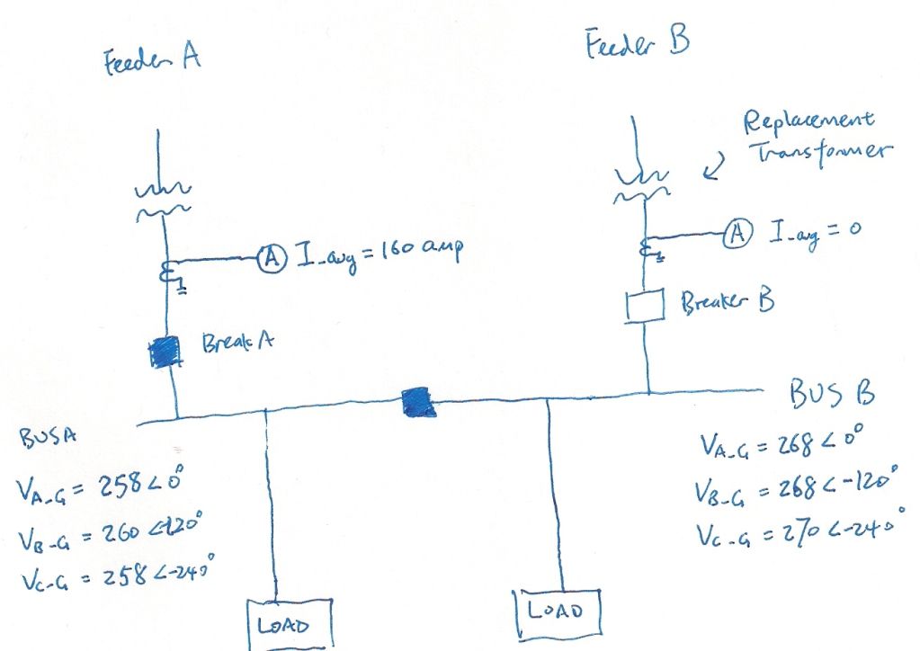
Shown below is a main-tie-main system. Breaker B is open. We're planning to close breaker B and then open the tie to restore the system to normal. The concern is from the voltage difference from the two feeder transformers (one was replaced after a failure, and the voltage had been adjusted to match as close as possible). All I know is that the total three-phase-average current from the bus A&B loads is 160amps.

So the question is: how to quantitatively calculate the circulating current once the tie breaker is closed?

Main_T_Main.jpg
 

Phil Corso

Senior Member
Tankfarms... Knowing the load parameters is helpful, but more important is knowing the capacities, impedances, and tap settings of both transformers. Do you have that info?

Regards, Phil Corso
 

Phil Corso

Senior Member
Circulating Current Between parallel xfmrs

Circulating Current Between parallel xfmrs

Tankfarms... Knowing the load parameters is helpful, but more important is knowing the capacities, impedances, and tap settings of both transformers. Do you have that info?

Regards, Phil Corso​
 

brian john

Senior Member
Location
Leesburg, VA
Assuming the transformers are matched it is not unusual to have a voltage difference due to voltage drop between the system with load and the system with no load, though 10 volts seems a bit high.
 

tankfarms

Member
Tankfarms... Knowing the load parameters is helpful, but more important is knowing the capacities, impedances, and tap settings of both transformers. Do you have that info?

Regards, Phil Corso

Phil Corso,
Thanks for looking into this for me:
Transformer A: 2400/480V, delta-delta with no phase shift, 500KVA, Z% = 5.8,
Transformer B: 2400/480V, delta-delta with no phase shift, 500KVA, Z% = 5.7,

Transformer B started with higher voltages, so we are using its lowest tap setting now which gives the line-gnd. voltages as indicated. Due to the continuous supply of electricity from transformer A, we simply can't touch A's tap setting.
 

ron

Senior Member
tankfarms,

Although you show V line-G as angle 0, are you sure that a voltage measurement from feeder A phase A to feeder B phase A is only 10V? Is it possible that things could be made worse that phase A from one feeder is not synchronized to phase A from feeder B?

I think we can theoretically figure this out, but I'm curious if you could tell why we care? The secondary breaker is likely an 800A, and the imbalance current will be <<800A as long as the sources are synchronized.
 

iceworm

Curmudgeon still using printed IEEE Color Books
Location
North of the 65 parallel
Occupation
EE (Field - as little design as possible)
... So the question is: how to quantitatively calculate the circulating current once the tie breaker is closed? ...

Why do you suspect you will have any circulating current? I can't pull up your picture - my system's problem not yours. Is there something else besides two transformers connected in parallel.

here's what I am thinking:
As you already know, if the turns ratios are equal, the transformers will share at the ratio of the impedances.

But you don't know the turns ratios - which is the same as you don't know the open circuit voltage of the on-line, loaded transformer. Although you can get close by looking at the tap setting and the nameplate.

If you didn't have any load, you could push current from the higher set secondary to the lower set secondary. Is this the circulating current of concern?

But you do have load. And you have set the unloaded transformer terminal voltage close to, but above the terminal voltage of the loaded transformer. Is the concern that one xfm will be back-fed and the other, loaded xfm will trip? As Phill said, you will need the xfms base, impedance, turns ratio (at the tap setting chosen). Some of that may be hard to get.

ABB, Electrical Transmission and Distribution Reference Book has two pages explaining the parallel xfm model. It looks about like the attached.
View attachment Parallel xfm model.pdf

When paralleled, there may be a slight rise in the terminal voltage as the on-coming xfm picks up part of the load Close the Secondary main, take time to measure the before and after currents, open the tie.

ice
 

Phil Corso

Senior Member
Tankfarms… the simple equation for maximum circulating–current between paralleled transformers at the instant the tie-breaker is closed is:
Ic = ∆V / Zt = ∆V / (Za + Zb), where:
o Ic = Circulating-current in Amps.
o ∆V = Difference between Xfmr A’s term’l-voltage & Xfmr B’s term’l-voltage (Avg ~10V.)
o Za = Xfmr A’s Impedance, in Ω’s (not % or per-unit.)
o Zb = Xfmr B’s Impedance, in Ω’s (not % or per-unit.)

As intimated by Brian, the existing voltage-differences are probably due to A carrying the entire load, while B is unloaded. Thus, circulating-current will decrease after the initial value upon breaker closure. That is, as soon Xfmr B picks up its share of load its terminal voltage will tend to drop.

Also note that circulating-current will be mostly reactive, if both A & B xfmrs have X/R ratios typical for 500kVA rating


Tankfarms, do you need help with converting % Impedance to Ohms?

Regards, Phil Corso
 
Last edited:

iceworm

Curmudgeon still using printed IEEE Color Books
Location
North of the 65 parallel
Occupation
EE (Field - as little design as possible)
The &^%^%*)((*&^%%$ thing won't let me edit, try this version


... So the question is: how to quantitatively calculate the circulating current once the tie breaker is closed? ...

Why do you suspect you will have any circulating current? I can't pull up your picture - my system's problem not yours. Is there something else besides two transformers connected in parallel.

Here's what I am thinking:
As you already know, if the turns ratios are equal, the transformers will share at the ratio of the impedances.

But you don't know the turns ratios - which is the same as you don't know the open circuit voltage of the on-line, loaded transformer. Although you can get close by looking at the tap setting and the nameplate.

If you didn't have any load, you could push current from the higher set secondary to the lower set secondary. Is this the circulating current of concern?

But you do have load. And you have set the unloaded transformer terminal voltage close to, but above the terminal voltage of the loaded transformer. Is the concern that one xfm will be back-fed and the other, loaded xfm will trip? As Phill said, you will need the xfms base, impedance, turns ratio (at the tap setting chosen). Some of that may be hard to get.

ABB, Electrical Transmission and Distribution Reference Book has two pages explaining the parallel xfm model. It looks about like the attached.
View attachment 6958

A suggestion if the management wants to see a calculation. Use a similar model to the one attached. Caluclate the on-line xfm open circuit voltage. And you know the off-line xfm open circuit voltage. You should be able to then come up with a number for how the xfms will share the connected load.

After the manage nods their collectice corporate head, parallel them. When paralleled, there may be a slight rise in the terminal voltage as the on-coming xfm picks up part of the load Close the Secondary main, take time to measure the before and after currents, open the tie.

just thinking - not telling

ice
 

rbalex

Moderator
Staff member
Location
Mission Viejo, CA
Occupation
Professional Electrical Engineer
As mentioned by others, assuming the transformer impedances are well matched and their secondary voltages are fairly well synchronized, the circulating currents will be tolerable. However, you may still run afoul of Section 110.9, first paragraph, especially if the transfer isn’t entirely automatic after initiating it; i.e.,"automatic" means the “Tie”-Breaker opens automatically after the “B” breaker closes with no intentional delay. The interrupting duties of all overcurrent devices at the secondary system level must be sized for the contribution of both transformers – even for the overcurrent devices that won’t actually “see” the full fault currents. Section 110.9 makes no provision for “temporary” paralleling.

Assuming critical loads are redundant between the “A” and “B” busses, your best strategy is to move all critical loads to the “A” bus before initiating transfer, open the “Tie”- breaker, close the “B”-breaker, redistribute the loads as necessary.
 
Last edited:

tankfarms

Member
tankfarms,

Although you show V line-G as angle 0, are you sure that a voltage measurement from feeder A phase A to feeder B phase A is only 10V? Is it possible that things could be made worse that phase A from one feeder is not synchronized to phase A from feeder B?

I think we can theoretically figure this out, but I'm curious if you could tell why we care? The secondary breaker is likely an 800A, and the imbalance current will be <<800A as long as the sources are synchronized.

Ron,
Answer to your first question: Yes, I'm certain that phase A on feeder A matches phase A on feeder B, same go with the other phases. If not synchronized, you'll see A LOT more than 10 volts.

Answer to your second question: I'm simply curious, and, as an electrical engineer, I'd like to quantify things when I can instead of just telling people "there'll be circulating current".
 

tankfarms

Member
The &^%^%*)((*&^%%$ thing won't let me edit, try this version


Why do you suspect you will have any circulating current? I can't pull up your picture - my system's problem not yours. Is there something else besides two transformers connected in parallel.

Here's what I am thinking:
As you already know, if the turns ratios are equal, the transformers will share at the ratio of the impedances.

But you don't know the turns ratios - which is the same as you don't know the open circuit voltage of the on-line, loaded transformer. Although you can get close by looking at the tap setting and the nameplate.

If you didn't have any load, you could push current from the higher set secondary to the lower set secondary. Is this the circulating current of concern?

But you do have load. And you have set the unloaded transformer terminal voltage close to, but above the terminal voltage of the loaded transformer. Is the concern that one xfm will be back-fed and the other, loaded xfm will trip? As Phill said, you will need the xfms base, impedance, turns ratio (at the tap setting chosen). Some of that may be hard to get.

ABB, Electrical Transmission and Distribution Reference Book has two pages explaining the parallel xfm model. It looks about like the attached.
View attachment 6958

A suggestion if the management wants to see a calculation. Use a similar model to the one attached. Caluclate the on-line xfm open circuit voltage. And you know the off-line xfm open circuit voltage. You should be able to then come up with a number for how the xfms will share the connected load.

After the manage nods their collectice corporate head, parallel them. When paralleled, there may be a slight rise in the terminal voltage as the on-coming xfm picks up part of the load Close the Secondary main, take time to measure the before and after currents, open the tie.

just thinking - not telling

ice

Thanks Iceworm, your last paragraph is very interesting!
 

iceworm

Curmudgeon still using printed IEEE Color Books
Location
North of the 65 parallel
Occupation
EE (Field - as little design as possible)
... However, you may still run afoul of Section 110.9, first paragraph, especially if the transfer isn?t entirely automatic after initiating it; i.e.,"automatic" means the ?Tie?-Breaker opens automatically after the ?B? breaker closes with no intentional delay. The interrupting duties of all overcurrent devices at the secondary system level must be sized for the contribution of both transformers ? even for the overcurrent devices that won?t actually ?see? the full fault currents. ....

Bob -
It's a pair of 500kva, 480V, 5.7%Z transformers. Even with infinite bus they are 10kA SSC a piece. If their engineer says it's okay to close them, it would be okay with me.

ice
 

tankfarms

Member
As mentioned by others, assuming the transformer impedances are well matched and their secondary voltages are fairly well synchronized, the circulating currents will be tolerable. However, you may still run afoul of Section 110.9, first paragraph, especially if the transfer isn?t entirely automatic after initiating it; i.e.,"automatic" means the ?Tie?-Breaker opens automatically after the ?B? breaker closes with no intentional delay. The interrupting duties of all overcurrent devices at the secondary system level must be sized for the contribution of both transformers ? even for the overcurrent devices that won?t actually ?see? the full fault currents. Section 110.9 makes no provision for ?temporary? paralleling.

Assuming critical loads are redundant between the ?A? and ?B? busses, your best strategy is to move all critical loads to the ?A? bus before initiating transfer, open the ?Tie?- breaker, close the ?B?-breaker, redistribute the loads as necessary.

which document is being referred to here?
 

rbalex

Moderator
Staff member
Location
Mission Viejo, CA
Occupation
Professional Electrical Engineer
Bob -
It's a pair of 500kva, 480V, 5.7%Z transformers. Even with infinite bus they are 10kA SSC a piece. If their engineer says it's okay to close them, it would be okay with me.

ice
With motor contributions the total available fault is roughtly 22-25kA "... at the line terminals of the equipment." (Secton 110.9) Neither of the Mains nor the Tie will need to interrupt that, but they must be sized for it in a closed transition anyway; all of the downstream OCPs must be rated for it too.
 

Smart $

Esteemed Member
Location
Ohio
Yes, I'm certain that phase A on feeder A matches phase A on feeder B, same go with the other phases. If not synchronized, you'll see A LOT more than 10 volts.

...
Not necessarily true (assuming you are just taking the difference between the two voltage to ground measurements).

Being true is dependent on how the voltage angles are measured. When you have two isolated supplies, the voltage angles must be measured using the same reference... meaning, for example, a phase voltage from one supply must be used to measure the voltage angles of both.
 
Last edited:

iceworm

Curmudgeon still using printed IEEE Color Books
Location
North of the 65 parallel
Occupation
EE (Field - as little design as possible)
With motor contributions the total available fault is roughtly 22-25kA "... at the line terminals of the equipment." (Secton 110.9) Neither of the Mains nor the Tie will need to interrupt that, but they must be sized for it in a closed transition anyway; all of the downstream OCPs must be rated for it too.
Hummm ..... You want to add 2kA to 5KA for motor contribution. Where does that come from? As I recall, ieee purple book says to ignore any motors under 50 hp

As I recall the load is 160A - which I translated to 80A each side. How many 50hp motors do you think are on the system?

None of this matters. You are correct that some are translating the code to agree with you. The section has not changed since at least the 1997 (that's the oldest I have) - bu the translation sure has.

Lets talk about a more normal system, where the SSC matters. Say a double sub with a pair of 1500KVA, 5.0%Z. That can put 72kA to a close fault. And 72KA CsB can be hard to get over say 42KA

Yesterday no one knew it was a problem to quickly parallel and then open the tie. Today, some say we need automatic opening of the tie when the second feeder is closed or the CBs have to be rated for the fault current from transformers.

I contend that if there is a code violation, then it occured upon building/installing the unit. If the AHJ did not enforce the code translation requiring either automatic control of the tie or higher rated CBs, then there is no code violation at a later date when the AHJ suddenly changes their translation.

Now if you think it is dangerous, that's way different from illegal.

Just so I am clear: The NEC only counts the day the equipment is installed. After that it is OSHA. (and I don't know what OSHA says - I'm not dealing with double ended sub's these days)

And if I were installing one today - I'd put an automatic trip on the tie. Or get really fat breakers.

ice
 

iceworm

Curmudgeon still using printed IEEE Color Books
Location
North of the 65 parallel
Occupation
EE (Field - as little design as possible)
With motor contributions the total available fault is roughtly 22-25kA "... at the line terminals of the equipment." (Secton 110.9) Neither of the Mains nor the Tie will need to interrupt that, but they must be sized for it in a closed transition anyway; all of the downstream OCPs must be rated for it too.

Where did that come from?

I don't see any possible translation of 110.9 that says the main or the tie have to interupt more fault current than can be delivered.

Although, it would be unlikely that one would buy a switchboard braced for the high fault current and not buy CBs to match that.

ice
 
Status
Not open for further replies.
Top