blueheels2
Senior Member
- Location
- Raleigh, NC
- Occupation
- Electrical contractor
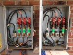
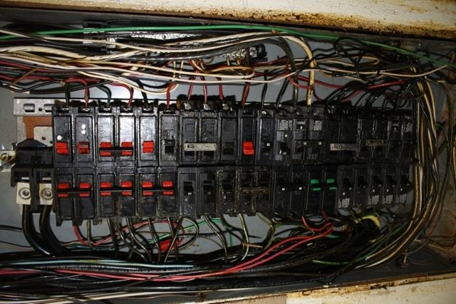
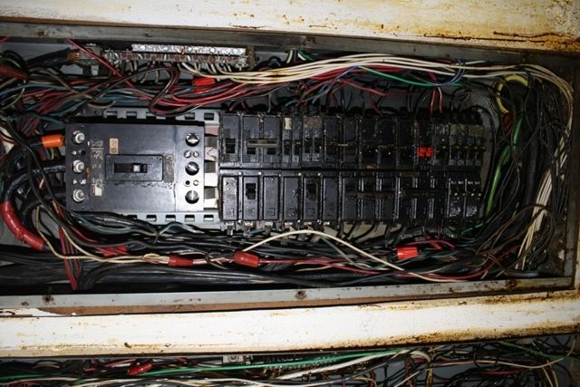
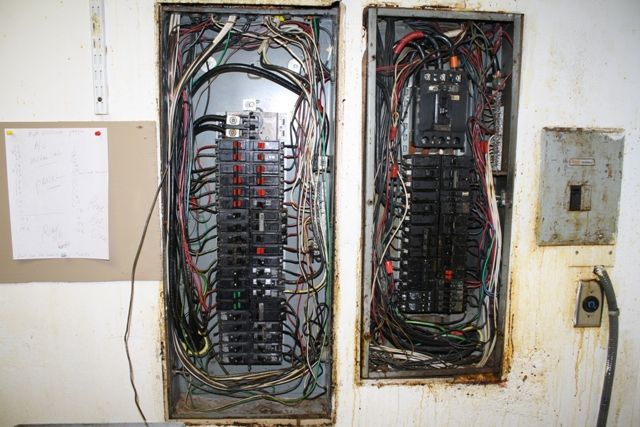
Just want to run this past those smarter than myself. Concrete floor, masonry wall cabin with 100 amp service. FPE main panel, No ground rods. Initially I looked and thought the can was bonded but after a shock last night I quit working and came back and did a thorough service investigation this morning. Surprise neutral was floating. One branch ckt neutral was landed on a ground bar. I added a 4 wire sub panel neutral ground separation. It looked initially like there was a bonding screw on the neutral bar so I went about my business as if things were okay. EMT between panels. Last night I was running EMT and was kneeling on the concrete (wet) when I got shocked. Today I am adding ground rods new feeder and new main panel. I believe this will clear up the problem. Am I missing anything. I assume I got shocked because my body was a better return path than my subpanel pipe and ground which was tied to the neutral. I know my pipe and ground gave me a false reading to the can from the floating neutral bar this morning. Hope this makes sense.