All,
Unsure if this is posted correctly, moderators step in...
I am attempting to re-wire a motor driven south bend lathe, EICOR made for FAIRBANKS-MORSE, which has no labelling or wiring diagram. The data plate has the following:
model: CS-73-26; 1/2 hp: 60 hz; 1725 rpm; 115/230 1 phase; currently operate at 115v.
The motor is on a aged southbend metal lathe, which dates to the '30's or 40's, which precedes me by a small margin. The attempt to make a reversible motor operation is keeping me from trying anything. I am afraid to make things worse, the motor works in forward.
The motor came with the lathe, which happens to be a shop lathe, sitting in a cramped corner, which now has importance; seeing as we've a "new" man in shop, but he's my senior and had at one time operated such a machine.
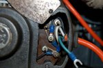
The NEMA configurations seem not to apply for this motor. Any help is appreciated, feel free to question what info I've provided. I've got 6 identified terminals on the motor, the #6 doesn't have a stud. Also, the drum switch is a furnas r12, which pre-dates me as well. The motor terminals are jumpered from 1 to 2, and 3 to 4, leaving five free and no area to land 6.
Any help with the motor diagram is thanked,
Google search has been fruitless.
D.
Unsure if this is posted correctly, moderators step in...
I am attempting to re-wire a motor driven south bend lathe, EICOR made for FAIRBANKS-MORSE, which has no labelling or wiring diagram. The data plate has the following:
model: CS-73-26; 1/2 hp: 60 hz; 1725 rpm; 115/230 1 phase; currently operate at 115v.
The motor is on a aged southbend metal lathe, which dates to the '30's or 40's, which precedes me by a small margin. The attempt to make a reversible motor operation is keeping me from trying anything. I am afraid to make things worse, the motor works in forward.
The motor came with the lathe, which happens to be a shop lathe, sitting in a cramped corner, which now has importance; seeing as we've a "new" man in shop, but he's my senior and had at one time operated such a machine.
The NEMA configurations seem not to apply for this motor. Any help is appreciated, feel free to question what info I've provided. I've got 6 identified terminals on the motor, the #6 doesn't have a stud. Also, the drum switch is a furnas r12, which pre-dates me as well. The motor terminals are jumpered from 1 to 2, and 3 to 4, leaving five free and no area to land 6.
Any help with the motor diagram is thanked,
Google search has been fruitless.
D.