jfouts
Member
- Location
- Union, OR USA
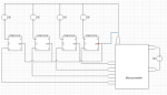
I am working a project to remote monitor a PLC panel for lamp status (On/Off).
Each lamp has its own 12VDC source voltage.
I have worked up a board with voltage regulators connected to the positive side of the lamps, in order to control the output voltage which then feeds a Raspberry Pi.
Typically I would connect all grounds together for a single common ground, but since these lamps are being fed from multiple different pieces of equipment on their own isolated circuits, should I be concerned about connecting all of my grounds together?
I don't know why I am second guessing myself on this one, I guess I am just looking for encouragement that I am not losing my mind.
")