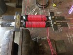
I wanted to demonstrate a simple transformer showing turns ratio with step up and step down. I found a little experiment on the web and came close to following the directions but those materials were not on hand so I continued with the experiment anyway. The original instructions ask for several hundred turns of 28 gauge mag wire and apply low voltage AC.
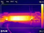
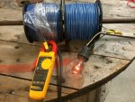
I used insulated 14cu. solid, 150 turns to 100 turns and connected to 120 VAC. The source breaker tripped. Moved source to the other winding with the same result. Tomorrow I plan to connect to a variac and start out at a much lower voltage. If you agree that a transformer is nothing more than conductors wrapped around a steel core, what are the mistakes I made?
The experiment was titled; Build a Transformer Chapter 4 - AC Circuits