You are using an out of date browser. It may not display this or other websites correctly.
You should upgrade or use an alternative browser.
You should upgrade or use an alternative browser.
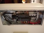
how would this main panel be grounded?
- Thread starter S-117
- Start date
- Status
- Not open for further replies.
kwired
Electron manager
- Location
- NE Nebraska
- Occupation
- EC
I'm guessing you meant 250.24 and not .22. .22 is circuits not to be grounded.
How do you tell? Where is the grounding electrode conductor? The POCO source is already grounded, but 250.24 still requires a GEC that can be connected anywhere mentioned in that article.
How good is your electrode is another issue and requires more than just a simple ohmmeter to test. NEC doesn't tell us how good the electrode needs to be other than for rod and pipe electrodes you must have two electrodes unless you can prove you have 25 ohms or less with just one electrode. Some jobs there may be design specs that tell how low the resistance of any electrodes must be, but that is above and beyond code minimum requirements.
- Location
- New Jersey
- Occupation
- Journeyman Electrician (retired)
The main bonding jumper (MBJ) is the green screw connecting the neutral bus to the enclosure. As long as that connection is sound the system should be properly grounded.
- Location
- Chapel Hill, NC
- Occupation
- Retired Electrical Contractor
The neutral is grounded so the only visual you need is the green screw. If the green screw is installed then the neutral/ground bar is connected to the panel casing as well as to the service neutral. No equipment grounding conductor is needed until you leave the main panel.
jaggedben
Senior Member
- Location
- Northern California
- Occupation
- Solar and Energy Storage Installer
The panel is bonded to the neutral with the green screw. That is a main bonding jumper, and correctly installed, assuming it is a service panel. (But is it?)
I see no evidence of grounding, i.e. I don't see a grounding electrode conductor, but maybe it's just hard to see in the photo. The grounding could also be allowed to be somewhere else.
It would be helpful to clarify some things:
- Is this really the service panel? (Looks like an odd place for one, in an interior wall with a larger living or dining room behind).
- What are conductors coming into the panel installed in? Metal raceway? It matters if this isn't actually the service equipment.
- Is there another place upstream where there is/could be a grounding electrode conductor?
romex jockey
Senior Member
- Location
- Vermont
- Occupation
- electrician
The MBJ location is often up to the poco, the NEC simply provides the means to accommodate
~RJ~
~RJ~
winnie
Senior Member
- Location
- Springfield, MA, USA
- Occupation
- Electric motor research
To add to what the others have said, the main bond at the service panel is essentially a 'bootleg ground'.
The term 'grounding' has multiple meanings. One is the connection of something to an electrode buried in the soil. The other is the _bonding_ of all metal that isn't supposed to be carrying current to _one_ of the circuit conductors. The purpose of this _bonding_ is to ensure than any fault between other circuit conductors and the 'non-current carrying metal' causes a short circuit which trips a breaker.
The circuit conductor that gets _bonded_ is also the circuit conductor that gets _grounded_, so the bonding is frequently called grounding, and the green wire that is supposed to carry fault current is called an 'equipment ground conductor'.
That green ground screw connects the grounded neutral wire to the enclosure. It is very similar to a jumper going from a neutral to a ground wire at a receptacle (a 'bootleg ground'). There is one _critical_ difference. You should only _bond_ a current carrying conductor to the ground system at _one_ location, and only _one_ location. When you bond at more locations then all that bonded metal, which is not supposed to be carrying current, ends up being in parallel with your neutral conductors.
You actually see this in practice, because the NEC mandates that you bond at one and only one location per service...but the power company provides many services with one transformer, and at each service the neutral gets grounded. In locations where one of the grounding electrodes is metal underground water piping, you often see a substantial amount of neutral current flowing on the plumbing.
Going back to the original question: if you are checking the _bonding_ you make sure that this panel is the one where you are supposed to have the bond, and then you check continuity across the ground screw. If you are checking the grounding electrodes then you look for the grounding electrode conductor and make sure it follows the appropriate rules to the appropriate electrodes.
-Jon
Strombea
Senior Member
- Location
- Prescott, Arizona, USA
As a rule of thumb the bonding to grounding electrode should be as close as possible to the meter or POCO entry. Doing this simplifies the answer as the feeders should be 4 wire to the distribution panel. In an All -in- One panel it all happens immediately thus the feeders are from manufacturer and bonding is via a buss. In your scenario there should be a visible 4th wire bonding to meter can.
- Occupation
- Licensed Electrician
Unless things are different in ypur state it is not up to the poco, it is totally up to the NEC right at the spot where the NEC takes over.The MBJ location is often up to the poco, the NEC simply provides the means to accommodate
~RJ~
- Occupation
- Licensed Electrician
As a rule of thumb the bonding to grounding electrode should be as close as possible to the meter or POCO entry. Doing this simplifies the answer as the feeders should be 4 wire to the distribution panel. In an All -in- One panel it all happens immediately thus the feeders are from manufacturer and bonding is via a buss. In your scenario there should be a visible 4th wire bonding to meter can.
?? The main bonding jumper is often just a screw.
ptonsparky
Tom
- Occupation
- EC - retired
Things don’t look right with all the half sized breakers, It appears that the Red & Black are both coming off the same phase. Are these supposed to be multi wire branch circuits?
I was was looking for the green screw...
eta. NM. I think I see where the spacing changes and I found the screw.
I was was looking for the green screw...
eta. NM. I think I see where the spacing changes and I found the screw.
Last edited:
ptonsparky
Tom
- Occupation
- EC - retired
I tried to edit the above but could not.
I found the spacing changes of the CBs so ignore my comments.
I found the spacing changes of the CBs so ignore my comments.
romex jockey
Senior Member
- Location
- Vermont
- Occupation
- electrician
Unless things are different in ypur state it is not up to the poco, it is totally up to the NEC right at the spot where the NEC takes over.
I guess i hail from a funky state then Dave.....
 ~RJ~
~RJ~LarryFine
Master Electrician Electric Contractor Richmond VA
- Location
- Henrico County, VA
- Occupation
- Electrical Contractor
Things don’t look right with all the half sized breakers, It appears that the Red & Black are both coming off the same phase. Are these supposed to be multi wire branch circuits?
They are GE 2p half-sized breakers, not tandems. Note the silver between handle pairs, as well as the positioning of the breakers.
ptonsparky
Tom
- Occupation
- EC - retired
They are GE 2p half-sized breakers, not tandems. Note the silver between handle pairs, as well as the positioning of the breakers.
I finally found the positioning but still can't see the silver. Regardless, I stand corrected.
- Status
- Not open for further replies.