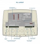
I suppose it comes down to if you want this device to be your complete control system......or if you want it to only automate what would normally be a manual process of swapping over to a standby pump, a situation that would normally require manually switching a selector switch and opening and/or closing some valves.
It looks like it is sold to be a complete control system. I would need a lot more information to be comfortable with it being so used. I much prefer to design and wire my own control systems, or use a few select vendors that have control schematics I approve of. For example, I don't approve of a flow switch as "proof of flow". Every one I have had experience with ends up with the paddle from the flow switch lodged in the impeller of the pump. For me, there are far better ways to go.
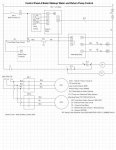
This is a subject near and dear to my heart and I have strong feelings on the matter. A well designed pump control system is virtually self-diagnostic if you know what to look for and quite tolerant of component and/or pump failures.
For example, if this device was your complete control system and you lost your 120 VAC input, would you get any failure alarms? Of course not, and that is totally unacceptable to me in my field of work.
Okay, I'll shut up now, because I could spew a lot more dogma about how a lift station vs a duplex air compressor/vacuum pump vs a boiler feed water system should be wired/controlled. And yes, I'm a dinosaur who wants no part of a PLC controlling my emergency generators.