Wiring Diagram Help

Status
Not open for further replies.

mbrooke

Batteries Included
Location
United States
Occupation
Technician
I'm confused here. Why is the motor overload only in the A phase? And how/why would a motor run open delta?
 

Attachments

  • diagram Freezer 1.jpg
    diagram Freezer 1.jpg
    101.8 KB · Views: 4

dkidd

Senior Member
Location
here
Occupation
PE
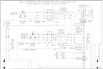
I think you are looking at the contactor coil, but I'm guessing. Can you mark it up? Which is A phase?
 

steve66

Senior Member
Location
Illinois
Occupation
Engineer
See terminal C on the motors, below it.

Are they possibly single phase motors with a run winding and a starting winding? So the start winding doesn't need OL since it opens as soon as the motor starts spinning?

Edit: After I look at it again, I think the OL is common to both the run and start windings, so it does protect both windings. And it looks like the OL drops out the contactor - that keeps the run and start windings from being energized in series across L2 and L3.
 

mbrooke

Batteries Included
Location
United States
Occupation
Technician
Are they possibly single phase motors with a run winding and a starting winding? So the start winding doesn't need OL since it opens as soon as the motor starts spinning?

Edit: After I look at it again, I think the OL is common to both the run and start windings, so it does protect both windings. And it looks like the OL drops out the contactor - that keeps the run and start windings from being energized in series across L2 and L3.

It went through my mind, but why connect it across a 3 phase supply?
 

synchro

Senior Member
Location
Chicago, IL
Occupation
EE
The TF5 suffix on the compressor numbers designates they are 3-phase. The suffix would be PF instead for single phase units. See the links below.
The schematic symbols for the compressors are for single-phase, but that's very likely to be incorrect based on the compressor model numbers and the rest of your schematic.


Compressor schematics on pg. 68 of pdf (pg. 65 of original document) at: www.hvacrinfo.com/Compressors/Scroll.pdf

https://climate.emerson.com/documents/new-copeland-scroll-zs-ka-compressors-en-2884468.pdf

https://opi.emersonclimate.com/CPID/GRAPHICS/Types/AEB/ae1387.pdf
 

mbrooke

Batteries Included
Location
United States
Occupation
Technician
The TF5 suffix on the compressor numbers designates they are 3-phase. The suffix would be PF instead for single phase units. See the links below.
The schematic symbols for the compressors are for single-phase, but that's very likely to be incorrect based on the compressor model numbers and the rest of your schematic.


Compressor schematics on pg. 68 of pdf (pg. 65 of original document) at: www.hvacrinfo.com/Compressors/Scroll.pdf

https://climate.emerson.com/documents/new-copeland-scroll-zs-ka-compressors-en-2884468.pdf

https://opi.emersonclimate.com/CPID/GRAPHICS/Types/AEB/ae1387.pdf


Incorrect drawing, thats what I'm thinking too. I can't picture a 3 phase compressor being wired like that internally.
 

Russs57

Senior Member
Location
Miami, Florida, USA
Occupation
Maintenance Engineer
The drawing stinks. The C, S, and R terminals indicate a single phase compressor but those aren't single phase. The compressors have internal protection. The windings are in a wye configuration and the thermal overload breaks the common connection point on all 3 phases.
 

mbrooke

Batteries Included
Location
United States
Occupation
Technician
The drawing stinks. The C, S, and R terminals indicate a single phase compressor but those aren't single phase. The compressors have internal protection. The windings are in a wye configuration and the thermal overload breaks the common connection point on all 3 phases.

Yup- I can't see many 3 phase motors in open delta.
 

LarryFine

Master Electrician Electric Contractor Richmond VA
Location
Henrico County, VA
Occupation
Electrical Contractor
My take is that the drawing is correct, and they use the third phase on the start winding instead of a start capacitor, and the motor runs as single-phase.

A 3ph-start/1ph-run motor, if you will. And there is no OL,
 

mbrooke

Batteries Included
Location
United States
Occupation
Technician
Upon closer examination, I see the OL in the motor, on the C terminal.

What's incorrect about my statement on the starting on the third phase?

If you trip one phase, then both the start and run wingdings will be in series still passing current.
 

steve66

Senior Member
Location
Illinois
Occupation
Engineer
The schematic symbols for the compressors are for single-phase, but that's very likely to be incorrect based on the compressor model numbers and the rest of your schematic.

Yes, they are for single phase motors - I just realized the third winding is missing :)

So either the motor diagram is wrong and its actually 3 phase, or the part numbers are wrong.

I don't see much point in analyzing it any farther. It could have just been a copy and paste error where the drafting person forgot to change the motor schematic.
 
Status
Not open for further replies.
Top