Problem about Relay Wiring

Status
Not open for further replies.

Hanalee

Member
Location
China, Hongkong
Occupation
Electronic Engineer
Hi, all
I am trying to repair the mess the prior owner made of the engine cooling fan system. At the front of the engine bay on the left side there is a panel of relays that from Steve’s maintenance tips I have identified as the fuel supply pump relay, the ECU relay and the radiator fan high/low relays. The prior owner of my vehicle must have been trying to diagnose a cooling fan problem without reading though this forum. What he did is totally remove the fuel pump relay socket. It must have broken off when he was replacing a relay I can only guess. With the wires pulled out of the socket he clipped them directly to the bottom of the relay and taped it to bracket so it didn’t jiggle around.

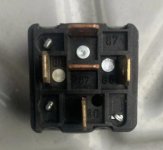
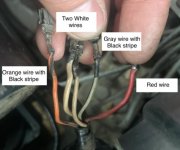
I fixed it myself according to Complete Relay Wiring Guide, but I failed. So I am going to replace the relay socket and repair all of this back to factory. I have already made arrangements to get a new socket and as long as they don’t fall through it should arrive in a few weeks. The problem I have is that when I pulled the relay off of these wires to replace the socket, I didn’t look at which tabs they slid onto at the bottom of the relay. My bad, I was just frustrated when I was working on it as there was a whole litany of other wiring snafus the prior owner had made and I just didn’t think to take a photo in the moment.

If anyone has a photo or can tell me which wire colors go to which tabs on the relay it would really help. I have attached some pictures to assist with what I am talking about.
 

Attachments

  • relay.jpg
    relay.jpg
    13.1 KB · Views: 19
  • color wires.jpg
    color wires.jpg
    31.9 KB · Views: 20

Hv&Lv

Senior Member
Location
-
Occupation
Engineer/Technician
I can’t help you but I couldn’t help but think to myself, “Electronic Engineer…., should be able to read schematic or simply figure it out..”

🤔 😆
 

FionaZuppa

Senior Member
Location
AZ
Occupation
Part Time Electrician (semi retired, old) - EE retired.
That relay is a std coil with C/NC/NO connections. What colored wires go to which relay blade, is like throwing darts.

The blades use some odd std for #'s (https://www.the12volt.com/installbay/forum_posts.asp?tid=83023)

My guessing, the white-blk-stripe is typically a chassis ground, ohm it to see. The red may be coil power, so maybe red is batt power via some other relay (volt meter it to see). The two whites and orange, no idea. Maybe these 3 are fan, one common and two coils.

From a fan speed perspective, I would assume lo speed to be the NC closed position, and hi speed on the NO position.

A wiring diagram is needed. I would also redo the wire connectors, they look a bit corroded.
 

petersonra

Senior Member
Location
Northern illinois
Occupation
engineer
years ago my housemate had the fan relay fail in his vw. he ordered a replacement from the local VW dealer but it was on back order and would not be in for several weeks. I bent a paper clip over and showed him how to stuff it into the relay socket and that is how he drove the car until he got the new relay. kind of a nuisance to have to open up the hood to insert the paper clip before starting and then to take it out after getting where he was going but much cheaper than a rental.
 

FionaZuppa

Senior Member
Location
AZ
Occupation
Part Time Electrician (semi retired, old) - EE retired.
years ago my housemate had the fan relay fail in his vw. he ordered a replacement from the local VW dealer but it was on back order and would not be in for several weeks. I bent a paper clip over and showed him how to stuff it into the relay socket and that is how he drove the car until he got the new relay. kind of a nuisance to have to open up the hood to insert the paper clip before starting and then to take it out after getting where he was going but much cheaper than a rental.
Those clips are not rated, but they still carry 12amps DC just fine, makes me wonder why we need #14 for 15amps 60Hz.
 

synchro

Senior Member
Location
Chicago, IL
Occupation
EE
I'm assuming that the relay pictured is the fuel pump relay even though you mentioned the radiator fan relay as well.

It looks like the upper two copper colored relay pins are both labeled "87" which indicates a normally open contact. Measure the resistance between these two pins to confirm that it's very low (in other words, they are internally connected together).

Pins 85 and 86 go to the internal relay coil, and when activated pin 86 should be at +12V and pin 85 close to 0V relative to engine/chassis ground. The polarity of the voltage across 85 and 86 can matter if there is an internal diode across them (used for clamping coil inductive kick-back).

Your picture seems to show that one of the white wires and the gray/black striped wire have a smaller cross sectional area than the other three. If that's true, then it's very likely that those two wires should go to terminals 85 and 86. But to confirm which wire goes to which of these terminals you should make a few measurements. Measure the voltage between the gray/black and small white wires with the ignition OFF, and then with it ON, noting which wire is positive relative to the other if you get a significant voltage. If you don't get 12V with the ignition ON then measure it with the key turned to START and the engine turning over (often the fuel pump is not activated without the engine turning over or running, for safety reasons). The wire which is +12V relative to the other should be connected to pin 86, and the more negative one to 85.

The red, orange/black striped, and one of the white wires look like they have a larger cross section than the other two wires mentioned above. If that is true then one of the larger wires should go to pin 30, and the other two should go to the 87 terminals (it shouldn't matter which of the 87 terminals if they are internally connected within the relay).
With the ignition switch turned OFF or the key removed, measure the voltage from each of these three larger wires relative to engine/chassis ground. I suspect only one wire will show +12V, and it should be connected to terminal 30. I'm guessing that this would be the red wire but it may not be. The other two larger wires should not have any significant voltage with the ignition OFF because one of them likely feeds the fuel pump, and the other possibly feeds the fuel injectors.
 
Last edited:

RumRunner

Senior Member
Location
SCV Ca, USA
Occupation
Retired EE
I'm posting this after synchro's post which should have been done prior. :(
If I'm reading you correctly, you're replacing the relay socket for the fuel pump . . .not for the cooling fan , right?

Some cooling fans are wired via the ECU while the fuel pump is wired "directly " through the ignition switch.
Those wires you pulled still have identifiable colors which is good.

As mentioned by Fiona, white is "generally" ground and red is power for the relay. So far that's what I had experience with and I agree.

So, according to your graphics you have five wires.
One wire with the colored tracing, two white wires that appear to be bundled together as one, one gray and one red. Total of five.

If we assume (and I agree with Fiona) the wires are identified as white (bundled) for ground, red for relay power.
The only wires that need to be identified are the orange with colored tracing and gray.
Since you don't have the schematic diagram . . .you can resort to the "red neck" style troubleshooting technique :)

Trace the wires that go to the fuel pump.
The colors should be the same at the relay all the way to the fuel pump.

If the color is not the same--it may be fed via ECU. . .which of course would require more work.
Normally the color changes when the wire is fed from the ECU to easily determine its origin.

BTW:
Looking at the picture of the relay socket, the two side by side vertical tabs are for relay power that are numbered 85 & 86. Normally except for some Mercedes Benz models , relays are NOT polarized.
Those polarized ones come with soldered-in diodes.

The middle vertical tab is the common (# 30 ) and the two horizontal contacts are NC (87a) & NO (87) contacts.
The same procedure would apply to the cooling fan.

Keep us posted when you get it fixed. . . learning is never ending quest.

Good Luck.
 
Status
Not open for further replies.
Top