Stevenfyeager
Senior Member
- Location
- United States, Indiana
- Occupation
- electrical contractor
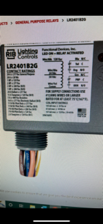
Supply power to the black & white.the relay I bought:
Thank you so much ! so in the diagram, I power up both the blk and orange wires with 120 v, ie, together ? And the yellow sends the 120 v to the load when switched ? And the dry switch just means it doesn't carry the 120 v but low voltage for communication. For 170' length for 3 - ways, 4 ways, low voltage switches, I would use 12-2 mc or can I use smaller wires between switches ? Sorry to ask all these but,... Also, I would need to use some kind of divider in a switch box or a separate switch box because of low voltage not being able to be with 120 v switches, correct ?Do you still have questions how?
You would need to keep your 3 & 4 ways isolated from other wiring per Class 2
Thank you. I did temporary wire it up like this using 3-way switches in my garage last night and it worked greatLook at the diagram. The two wires to the dry contact are now the feed to your switches, 3&4 ways, and the return back. Just as you would have in any switch loop. Do not apply any power to those two wires.
Power it up on your work bench. Don't worry about an actual load. Use a spool or two of any wire size to simulate the length of the switch loop. Short the control wires and listen for the relay. Both ends of a 250 coil of Romex would work.
Your RIB Ctrl circuit 120v, but what is the voltage rating of your class-2 thermostat wire?roughed in 400' of 4 wire thermostat wire
Your RIB Ctrl circuit 120v, but what is the voltage rating of your class-2 thermostat wire?
hm., thank you, but what about 310.10 H 1 ? the ampacity of each individual conductor is sufficient to carry the entire load... 300.3 C 1 sent me there.300.3 (C) (1)
the engineer on the phone told me 24 v DCYour RIB Ctrl circuit 120v, but what is the voltage rating of your class-2 thermostat wire?
") not!
not!Thank you. Sorry, I'm kind of slow... how do I mount this device,... whether I mount it on the top side of a light or outside of a junction box, the threaded fitting on it will feed both 24 v wires and 120v wires into the same "box." How does one keep them separate when there is only one exit from the device ?One has to have 300.3(C)(1) to continue on to use 310.10 (H) (1). Your counter salesperson stated what you need.
Another example was also mentioned.
Because of the Weird (reference to verbage on wire) aspect of Class 2 thermostat wire isn't listed in the low 310's, so your not suppose/ going to
combine them in a box. I'm sure there's plenty of wires that have been snuck around the isolation blades in device boxes.
Also mentioned was putting the RIB at the light and with power to light first and work backwards.
Class 2 has to be separated or even isolated from itself if not shielded.
Great concept possible weird wiring...
Thanks so much ! I've just never done this before.The RIB01BDC is UL Listed, and so a reasonable assumption is that the RIB's White/Red and White/Blue wires have an adequate voltage rating to be run along with wires that are at a 120V potential. To meet 300.3(C)(1), you could route the White/Red and White/Blue wires into a separate partition of the same box (or to another adjacent junction box) and connect them there to your thermostat wire. You could also connect these two RIB 24V wires to 120V rated wires or cable, and then route that to a connection made with the thermostat wires in a junction box at an arbitrary distance away from the RIB, if you so choose.