Ancient service panel

Status
Not open for further replies.

Jpflex

Electrician big leagues
Location
Victorville
Occupation
Electrician commercial and residential
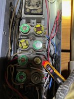
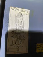
I’m not fully understanding the operation characteristics of this old style knob and tube, bulb fuse panel

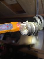
Obviously two busses for each phase feed power to center of old bulb style fuse but shouldn’t output branch circuit leg connect to threaded section of bull which would be separated only during the event of a short circuit by bulb fuse element?

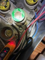
Instead I’m seeing center of bulb having voltage while directly connected to branch wires out. So where would the power separation be during a short?

Neutral is completed at center bus between lines. See pics
 

Attachments

  • 7A9CCD15-5FCA-4A3F-9F03-61E2F9E54D84.jpeg
    7A9CCD15-5FCA-4A3F-9F03-61E2F9E54D84.jpeg
    155.9 KB · Views: 53
Close up, center of fuse has voltage while being a solid piece to termination screw to right which likewise has power
 

Attachments

  • CCEA3F0F-22A2-4A8D-81D0-BE80806B7356.jpeg
    CCEA3F0F-22A2-4A8D-81D0-BE80806B7356.jpeg
    144.3 KB · Views: 19
Diagram
 

Attachments

  • 338802AF-D8D8-47C6-831F-2E1780A636E2.jpeg
    338802AF-D8D8-47C6-831F-2E1780A636E2.jpeg
    72.2 KB · Views: 20
Bulb fuse
 

Attachments

  • EA6741BC-FEA8-497D-8F7E-55A38299D5CE.jpeg
    EA6741BC-FEA8-497D-8F7E-55A38299D5CE.jpeg
    67.3 KB · Views: 11
FYI: I believe the proper term for that type fuse is "Plug" fuse.
You tester is likely showing voltage from that conductor adjacent to it or possibly feed-back from a 220 circuit.
Check the spot with a voltmeter.
The pictorial (diagram) seems pretty straight-forward.
 
I think I’ve narrowed it down. After examining it, the center screw does not have continuity with female screw section. Therefore bulb fuse connects center to screw shell to output branch terminating screw
 
FYI: I believe the proper term for that type fuse is "Plug" fuse.
You tester is likely showing voltage from that conductor adjacent to it or possibly feed-back from a 220 circuit.
Check the spot with a voltmeter.
The pictorial (diagram) seems pretty straight-forward.
The voltmeter is 3.8v ac between that termination branch circuit screw and neutral. I’m not sure why “voltage pen” is so sensitive to pick this up similar to phase voltage?

However I understand that center point is isolated from outer shell and branch circuit terminating screw although it does not look like it in appearance
 
Is not the center terminal from a lamp holder supposed to be line power and the outer female screw shell negative?

It has always been this way in my other encounters.

However black wire to lamp holder connects to outer shell of lamp holder while white wire goes to center terminal inside lamp holder shell. This would be opposite of what I would expect as outer shell would be live rather than center terminal inside of threaded female shell in lamp holder?

I disconnected fuses pier before doing continuity check

Were heat lamps done different or reversed years ago? There is no EGC wire as this setup was during knob and tube era
 

Attachments

  • E5CA886B-98B0-4559-809F-F5214A364CDF.jpeg
    E5CA886B-98B0-4559-809F-F5214A364CDF.jpeg
    91.8 KB · Views: 12
I think I’ve narrowed it down. After examining it, the center screw does not have continuity with female screw section. Therefore bulb fuse connects center to screw shell to output branch terminating screw
Yes that is how it works. The plug fuse connects the center to the screw shell and is in series with the load. Remove the fuse and the circuit is is opened, fuse blows and the circuit is open.

With really old fuse panels you need to be careful and make sure that the insulator between the screw shell and the center is actually in place. Years ago when doing demo of spaces with fuse panels we would blow the fuses by flashing the hot leg to the box or conduit. On one job I was whacking the #12 to the box and it wouldn't blow. Finally when I jammed it hard into the corner of the metal box it blew with quite a fireworks display. Turns out that the insulator between the two pieces of the fuse holder was missing and the fuse was doing nothing. When I grounded it out I ended up blowing the 100 amp fuse on the main.
 
FYI: I believe the proper term for that type fuse is "Plug" fuse. You tester is likely showing voltage from that conductor adjacent to it or possibly feed-back from a 220 circuit. Check the spot with a voltmeter. The pictorial (diagram) seems pretty straight-forward.
Also known as Edison base fuse.
 
Yes that is how it works. The plug fuse connects the center to the screw shell and is in series with the load. Remove the fuse and the circuit is is opened, fuse blows and the circuit is open.

With really old fuse panels you need to be careful and make sure that the insulator between the screw shell and the center is actually in place. Years ago when doing demo of spaces with fuse panels we would blow the fuses by flashing the hot leg to the box or conduit. On one job I was whacking the #12 to the box and it wouldn't blow. Finally when I jammed it hard into the corner of the metal box it blew with quite a fireworks display. Turns out that the insulator between the two pieces of the fuse holder was missing and the fuse was doing nothing. When I grounded it out I ended up blowing the 100 amp fuse on the main.

Your description reminded me of my apprenticeship ... that's how my journeymen found the circuit breaker !
 
I believe the proper term for that type fuse is "Plug" fuse.
Yes, Edison base fuse.

A plug fuse to me is either the British plug with a fuse inside, or the Hubble two fuse plug found on ham radio equipment from the 50s and 60s, think christmas tree light plug with those two small 3 amp fuses, but a plug large enough for two AGC fuses. ;)
 
Yes that is how it works. The plug fuse connects the center to the screw shell and is in series with the load. Remove the fuse and the circuit is is opened, fuse blows and the circuit is open.

With really old fuse panels you need to be careful and make sure that the insulator between the screw shell and the center is actually in place. Years ago when doing demo of spaces with fuse panels we would blow the fuses by flashing the hot leg to the box or conduit. On one job I was whacking the #12 to the box and it wouldn't blow. Finally when I jammed it hard into the corner of the metal box it blew with quite a fireworks display. Turns out that the insulator between the two pieces of the fuse holder was missing and the fuse was doing nothing. When I grounded it out I ended up blowing the 100 amp fuse on the main.
Assuming the material holding the fuses are non conductive ceramic etc there would be no voltage being present on service panel metal if insulating busing was worn or missing between center pin and outer shell as you described but if material holding fuses was conductive, I believe whole panel would be powered or have potential in this situation.

For whatever reason the lamp holder, a load from this panel has a white and black factory fixture wire in reverse from what I’m used to?

I did a continuity check to panel with fuse out and line and neutral are not reversed but color on lamp holder appears wrong/ reversed

I’m going to get a new lamp holder and wire line to center pin and neutral to outer shell of lamp holder. I do not understand why leads are reversed. Or maybe they were installed as jumpers wrong
 

Attachments

  • 6E9BCEBA-DD69-4F35-AAA7-65B24FB3EBC7.jpeg
    6E9BCEBA-DD69-4F35-AAA7-65B24FB3EBC7.jpeg
    77.3 KB · Views: 11
Yes, Edison base fuse.

A plug fuse to me is either the British plug with a fuse inside, or the Hubble two fuse plug found on ham radio equipment from the 50s and 60s, think christmas tree light plug with those two small 3 amp fuses, but a plug large enough for two AGC fuses. ;)
I see two branch line circuits terminating on one screw from output of fuse plug (branch circuit output load side) Could this have been allowed years ago?
 
It appears to me that all of the fuses have a 30A rating. I would check the wire gauge going to each fuse to make sure that it hasn't been "over fused". It hard to tell for sure from the pictures, but it looks like there are wires smaller than the 10 AWG appropriate for a 30A fuse.

The type W and type TL fuses that are being used have an Edison bases. There really should be adapters inserted into the fuse sockets that will reject a type S fuse that does not have the appropriate ampere rating for the branch circuit.
For example:
https://www.gordonelectricsupply.co...ype-Fuse-Adapter/6035042?text=SAO015&lsi=true
 
I see two branch line circuits terminating on one screw from output of fuse plug (branch circuit output load side) Could this have been allowed years ago?
Not so much allowed, as common retrofit situation. But, no it was not a rule years ago for one wire under one screw. I can not tell you how many duplex receptacles I have pulled out with 6 or eight wires on the 4 screws! Switches the same way, two or more wires under one screw. Passed inspection way back when.
 
Is not the center terminal from a lamp holder supposed to be line power and the outer female screw shell negative?
A lampholder and a fuseholder are two different things circuit wise. On a fuseholder both terminals are "hot", just one is LINE and the other is LOAD, with the screw shell the LOAD. With the Edison fuse removed, the shell should be "off", no longer hot. It should even be "off" as soon as the Edison fuse is unscrewed enough to open the bottom contact.

A lampholder should be neutral on the screw shell. But I came along when the table lamps had non-polarized plugs so at any given time it was 50/50 chance of the screw shell (not the "brass" shell that says "Press Here", that should have insulating paper inside it) being the hot wire.

Now if you are looking at a ceiling keyed or keyless fixture, many were wired backwards years ago, since no inspector would bother to remove an installed lampholder to check the wiring. ;)
 

Attachments

  • ED71CF13-3803-4EC1-BEB3-1596562F9494.jpeg
    ED71CF13-3803-4EC1-BEB3-1596562F9494.jpeg
    60.5 KB · Views: 4
Status
Not open for further replies.
Top