Can Use Some Help-Existing 200A Service with Solar. Connecting Level 2 EV Charger. Any Concerns?

Status
Not open for further replies.

Amps

Electrical Contractor
Location
New Jersey
Occupation
Electrical, Security, Networks and Everything Else.
Hello All,
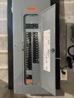
Thanks in advance for your comments and experience. A potential residential customer wants a level 2 EV charger circuit for his Tesla. The main service is 200A- 120/240. There are standard circuits and 2 central AC units, other appliances are gas. There is a back feed 2pole breaker in the panel with a label indicating a second source of power, solar. I have not installed a level 2 EV charger in this type of system. Is there anything I need to do other than connect the circuit in the panel as usual? Also wondering what could happen if the Tesla is charging and the utility goes out and the solar takes over. Can the solar be overloaded? Will the Tesla's smart charging adjust as needed? I have zero experience with solar and have no idea what could happen to the invertor, if anything.
 
There is a back feed 2pole breaker in the panel with a label indicating a second source of power, solar. I have not installed a level 2 EV charger in this type of system. Is there anything I need to do other than connect the circuit in the panel as usual?
There's one thing to do, which is to confirm which of the options in NEC 705.12 is being used to protect the busbar that has two supplies, namely the utility supply and solar supply. And that's because one of those options is "the sum of the breakers other than the main is no more than 200A (the busbar rating)." In which case you might be limited in the size of the breaker you can install for the EVSE.

However, that's pretty unlikely, and 705.12 requires a specific warning label to be put on the panel cover if that option is being used. The most likely option is that the backfed breaker is 40A or less, and that it's at one end of the bus, and the utility supply comes in at the other end of the bus, or the middle. In which there should be a "don't move this breaker" label next to the PV breaker, and the only special consideration is to, in fact, not move that breaker.

Also wondering what could happen if the Tesla is charging and the utility goes out and the solar takes over.
If the install is solar only, with no battery storage, that can't happen. Solar only uses an interactive inverter that only runs when the grid is up. When the grid goes down, the solar inverter stops working. This is for simplicity, as keeping the solar working during an outage is much more complicated.

Cheers, Wayne
 
First thing to do is a load calc to make sure you have the capacity. Solar isnt relevant for that. Being mostly gas you are probably fine even with two AC units (but why so much gas if you have solar??). How big of a level II charger does he want - 40A, 50A, 60A, or 100A?
 
There's one thing to do, which is to confirm which of the options in NEC 705.12 is being used to protect the busbar that has two supplies, namely the utility supply and solar supply. And that's because one of those options is "the sum of the breakers other than the main is no more than 200A (the busbar rating)." In which case you might be limited in the size of the breaker you can install for the EVSE.

However, that's pretty unlikely, and 705.12 requires a specific warning label to be put on the panel cover if that option is being used. The most likely option is that the backfed breaker is 40A or less, and that it's at one end of the bus, and the utility supply comes in at the other end of the bus, or the middle. In which there should be a "don't move this breaker" label next to the PV breaker, and the only special consideration is to, in fact, not move that breaker.


If the install is solar only, with no battery storage, that can't happen. Solar only uses an interactive inverter that only runs when the grid is up. When the grid goes down, the solar inverter stops working. This is for simplicity, as keeping the solar working during an outage is much more complicated.

Cheers, Wayne
Wayne, thank you so much for your help. It makes much more sense now that you explained it. The job is over an hour away so I requested a photo of the main panel before I take the ride to do the estimate. In the photo I saw the breaker for the solar and wasn't sure what to do. Attached is a photo showing the solar breaker located on the opposite end of the bus as you stated. A thousand thank you's!
 

Attachments

  • panel.jpg
    panel.jpg
    196.4 KB · Views: 18
First thing to do is a load calc to make sure you have the capacity. Solar isnt relevant for that. Being mostly gas you are probably fine even with two AC units (but why so much gas if you have solar??). How big of a level II charger does he want - 40A, 50A, 60A, or 100A?
Thank you Mark. I'm not sure about the size of the EV charger yet. since it's an hour away, not seeing the job in person yet, I requested a photo of the main panel from the owner. The only 2pole breakers are for AC, according to the index. And the 2pole for the solar. I do see a sump pump in the index too. I'm not sure what size level II charger he wants yet. I'm guessing 60A since I did one last year for a neighbor of his who also has a Tesla. Thank you for your help with this!
 

Attachments

  • panel.jpg
    panel.jpg
    196.4 KB · Views: 10
Thank you Mark. I'm not sure about the size of the EV charger yet. since it's an hour away, not seeing the job in person yet, I requested a photo of the main panel from the owner. The only 2pole breakers are for AC, according to the index. And the 2pole for the solar. I do see a sump pump in the index too. I'm not sure what size level II charger he wants yet. I'm guessing 60A since I did one last year for a neighbor of his who also has a Tesla. Thank you for your help with this!

Tesla used to sell a Wall Connector that would charge up to 80A (100A circuit required). The biggest one they sell now is 48A (60A circuit).
 
In the picture, that panel cover has 42 openings. Is that something Square D does, use the same panel cover for 42 space 3 phase panels and 40 space single phase panels? That would explain why the solar breaker is not in the last opening on the panel cover, because the last opening has no bus slot behind it.

Cheers, Wayne
That's certainly something manufacturers do sometimes.
It's possible it's this panel which comes in both a 40 and 42 space version.
 
Is there any real result in positioning the solar feed at the other end of the main bus from the utility feed? Are solar electrons going to flow up the bus and feed the local circuits, with any excess back-feeding the utility? If both feeds are at the same end, will the mix of electrons use more utility power even if there is sufficient solar power?
 
Is there any real result in positioning the solar feed at the other end of the main bus from the utility feed?
Yes, it will reduce I2R heating in the bus itself, by ensuring that, other than short term overloading within the trip curve(s) of the breaker(s), no part of the bus gets a current higher than max(solar breaker, utility breaker). Whereas if you put them side by side at the same end, you can get at most sum(solar breaker, utility breaker). [And less in practice.]

Are solar electrons going to flow up the bus and feed the local circuits, with any excess back-feeding the utility? If both feeds are at the same end, will the mix of electrons use more utility power even if there is sufficient solar power?
The electrons can't be labeled, so your questions are unanswerable.

Power is a simple balance sheet: power from utility = power demanded by loads - power supplied by the PV.

Cheers, Wayne
 
Is there any real result in positioning the solar feed at the other end of the main bus from the utility feed? Are solar electrons going to flow up the bus and feed the local circuits, with any excess back-feeding the utility? If both feeds are at the same end, will the mix of electrons use more utility power even if there is sufficient solar power?
The circuits are in parallel and the electrons will be allocated to the loads according to their impedances. Any electrons which are not required to service the loads will be absorbed by the grid. The loads do not know or care from whence their allotted electrons come.
 
Status
Not open for further replies.
Top