Hi I was wondering if anyone had a recommendation for an automatic transfer swtch (ATS) that can be setup to use a main 240VAC input until it is unavailable and seamlessly switch to a second 240VAC input with phase sync so nothing gets interrupted. and if possible, then return to the first input when it's available again - does this exist? just planning on 500W max of LED lighting and 2 laptops as the load, no inductive load anyway - maybe some capacitance.. I think..but trying to avoid any flicker/spikes. thanks!
You are using an out of date browser. It may not display this or other websites correctly.
You should upgrade or use an alternative browser.
You should upgrade or use an alternative browser.
ATS for single phase circuit <1000W resistive loads
- Thread starter jwgorman
- Start date
- Status
- Not open for further replies.
LarryFine
Master Electrician Electric Contractor Richmond VA
- Location
- Henrico County, VA
- Occupation
- Electrical Contractor
Welcome to the forum.
I believe you want a dual-conversion UPS, which runs on the battery all the time for seamless switching.
I believe you want a dual-conversion UPS, which runs on the battery all the time for seamless switching.
ptonsparky
Tom
- Occupation
- EC - retired
It's the way to go.Welcome to the forum.
I believe you want a dual-conversion UPS, which runs on the battery all the time for seamless switching.
The laptops should not be an issue as they already have batteries.
ptonsparky
Tom
- Occupation
- EC - retired
500 watts of LED is a lot of light
Birken Vogt
Senior Member
- Location
- Grass Valley, Ca
You can't do phase sync with a second source if you have to transfer instantly on loss of the first source. It either has to transfer immediately, or pause in neutral to give things a chance to stop. Because you can't control whether it happens to be in sync when the power goes down.
On retransfer you can wait as long as you need for sync to occur.
On retransfer you can wait as long as you need for sync to occur.
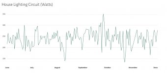
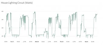
OK thanks! I see what you mean - the house lighting circuit really maxes out around 335W but what I'm looking to do is build up a 48VDC battery and use it as long as I can (via an inverter) until the software measuring it says it's too low and then throw a relay, causing the ATS to react and transfer to the other AC input.
It is mostly lighting so no it's not a big deal - but later there might be other small resistive loads you don't really want to interrupt - if possible. These might include the internet router in the house (around 15W). I agree it does add a lot of cost but the goal is that you could add solar safely, have some resiliency in times of no grid power, and also have solar even when the grid goes out (rare but grid-connected inverters generally turn off in that case). again it doesn't have to power the lights the whole time - like in winter when there is not as much sun clearly - but it could displace some of that load over the year.
Attachments
ruxton.stanislaw Spammer
Suspended Member
- Location
- Arkansas
- Occupation
- Laboratory Engineer
In the I.T. world, Tripp Lite makes these:


You can do the same yourself with a couple contactors (lock out one with the other using N/O and N/C aux), if you want to. Thanks to the juicy capacitors they have, most switching power supplies in a computer give you a few AC cycles, or even a significant fraction of a second (I recall there was some standard minimum length of time introduced back in the day for ATX), before they turn off.
You can do the same yourself with a couple contactors (lock out one with the other using N/O and N/C aux), if you want to. Thanks to the juicy capacitors they have, most switching power supplies in a computer give you a few AC cycles, or even a significant fraction of a second (I recall there was some standard minimum length of time introduced back in the day for ATX), before they turn off.
synchro
Senior Member
- Location
- Chicago, IL
- Occupation
- EE
You said: "-the house lighting circuit really maxes out around 335W but what I'm looking to do is build up a 48VDC battery and use it as long as I can (via an inverter) until the software measuring it says it's too low and then throw a relay, causing the ATS to react and transfer to the other AC input."
It seems like an inverter/charger from Victron would fit the bill since it has an internal transfer switch. They have models for 230VAC and a 48VDC input. One good thing about them is that they typically can supply a surge current of about 2X their continuous current rating, which most inverters fall far short of. This might be good for LED loads that can draw higher peak initial currents to charge the capacitors of their driver circuits.
https://www.victronenergy.com/inverters-chargers
I believe that they achieve their high surge current by directly pulse width modulating the battery voltage to create a 50 or 60 Hz waveform after filtering, and then boost the voltage up to 230V in a toroidal transformer. Other inverters boost the DC voltage with a DC/DC converter first before feeding a PWM inverter, which is likely cheaper and certainly lighter weight without a 50/60 Hz transformer, but it doesn't have the surge current capacity of an inverter fed directly from a battery.
If you're from Auckland, NZ it looks like this a local Victron distributor:
https://www.lusty-blundell.co.nz/page/19/contact-us
Last edited:
cool thanks that Tripp-Lite unit looks useful and in the right price range too - am wondering if there is a 240VAC model equivalent for 50Hz circuits. and yes the Victron gear does look very good especially if you can read and write the Ve.Direct protocol - thanks! I am using a 375W 48V Victron pure-sine inverter as a basic test unit right now and it's pretty solid but maybe a little underpowered (and no charger or ATS built in!)
this is a really important detail - yeah is that high initial current described a rule of thumb multiple? my sample rate on the data might not be fast enough at the moment to detect this...LED loads that can draw higher peak initial currents to charge the capacitors of their driver circuits
synchro
Senior Member
- Location
- Chicago, IL
- Occupation
- EE
LED loads that can draw higher peak initial currents to charge the capacitors of their driver circuits.
this is a really important detail - yeah is that high initial current described a rule of thumb multiple? my sample rate on the data might not be fast enough at the moment to detect this...
I don't know if there there's a rule of thumb for the peak initial current of LED lights, since there's so much variability between the simple circuitry inside LED bulbs and the more sophisticate drivers in light fixtures that have good power factor and low THD. Perhaps you could assume about a 3X factor for an initial surge current over the steady state current draw, based for example on a reduction by 1/3 in the current rating that Leviton smart switches have for LEDs vs. general purpose loads (as mentioned in the post linked below). I don't know how good of an estimate this would be, but it's certainly better than ignoring the peak current altogether.
https://forums.mikeholt.com/threads/dont-control-receptacle-with-smart-switch.2579267/post-2899334
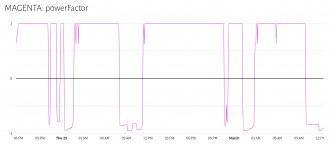
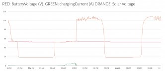
ok thanks @synchro I have my CT around backwards (will flip that) measuring the AC power usage on the 375W inverter but powerFactor should be 0.85 - 0.90 range - this is at 60-sec sample intervals so stuff could be happening at higher resolution. But you can see the charge controller filling the battery yesterday (Green is charging current (A) on the Morningstar TS-45 charge controller) but because it's now full, no charging current today - letting the solar voltage go to VOC. what I don't have yet is battery SoC.
Attachments
It might be that you failed to appreciate what the first response to your post suggested. Buy a double-conversion UPS and your problem is solved! Bluntly, the said UPS configuration supplies your power needs, the equipment decides which source to draw power from, no transfer spikes or switching peaks.
From Researchgate:

From Researchgate:
ruxton.stanislaw Spammer
Suspended Member
- Location
- Arkansas
- Occupation
- Laboratory Engineer
There most certainly are 240 V models! Tripp Lite specifically makes them for the U.S., however, they use IEC C13 outlets as that is standard for datacenters that often use 208Y/120 V (L - L) or 433Y/250 V (L - N) at the rack. You can plug them directly into I.T. equipment with the right cables or make up your own. Quality cables can be found for around the same price as a normal NEMA 5-15P or 6-15P cable in my experience.cool thanks that Tripp-Lite unit looks useful and in the right price range too - am wondering if there is a 240VAC model equivalent for 50Hz circuits. and yes the Victron gear does look very good especially if you can read and write the Ve.Direct protocol - thanks! I am using a 375W 48V Victron pure-sine inverter as a basic test unit right now and it's pretty solid but maybe a little underpowered (and no charger or ATS built in!)
- https://www.amazon.com/Tripp-Lite-200-240V-Rack-Mount-PDUMH20HVAT/dp/B0094TCQDW
- https://www.amazon.com/Tripp-Lite-Monitored-Auto-Transfer-WEBCARDLX/dp/B09GH83B4S
- https://www.amazon.com/IEC320-Extension-Adapter-adapter-Connector/dp/B078K63F89
While an online UPS with the right type of battery meant to be discharged all the time (e.g. LiFePO4) would also work, the ATS is going to be more cost effective. This is from South America, but it's rated for 16 A at 250 V: https://www.electropar.com.py/producto/switch-de-transferencia-estatica-sts-16a . You should find similar from I.T. or electric distributors in any country.
Last edited:
Thanks @ruxton.stanislaw these look great. Also I totally see the value in a double conversion UPS for most of my requirements, it's an already done/field tested solution and is probably the right answer for most people. the extra requirements I have in this experiment is that the scheduling of the energy needed for loads (what source they are powered from) may change depending on solar level, weather forecasts, even demand response value. that logic can have a few different inputs which we're still working on
ruxton.stanislaw Spammer
Suspended Member
- Location
- Arkansas
- Occupation
- Laboratory Engineer
It might void the manufacturer warranty, but you can do whatever you want in terms of modifying most UPS units, as long as you provide the correct DC voltage to it. If you are supplying regulated photovoltaic input (e.g. think DC-DC converter) and battery pack power to the UPS, it could run forever in theory as long as it has adequate cooling. They may not be engineered for those sort of hours, but a decent quality model should do the trick. Good cooling is key to extending the lifetime of the solid state components.ok thanks @topgone and @LarryFine - with a double-conversion UPS, can you choose your battery size, and also charge the batteries from a solar charge controller? I am looking into them now.
- Status
- Not open for further replies.