I saw that in the Ryan Jackson video I mentioned. He calculated the ohms in order to find ampacity for a 208V water heater like you said. How many people sizing water heater conductors and ocpd in the field do you think are doing that though. I feel that is high level. (Which I want to be)It helps to remember that, for purely resistive loads, the ohms are what's constant, not the watts. If you do the algebra, you can prove that the watts for resistive loads are proportional to the square of the voltage. So a 4 kW, 240V water heater will draw 3 kW at 208V.
You are using an out of date browser. It may not display this or other websites correctly.
You should upgrade or use an alternative browser.
You should upgrade or use an alternative browser.
Ohms law
- Thread starter Pinnie
- Start date
LarryFine
Master Electrician Electric Contractor Richmond VA
- Location
- Henrico County, VA
- Occupation
- Electrical Contractor
I am an electrician who understands a lot of theory and likes to teach.is anyone here an electrician or are you all engineers?
Ask a specific question and I will do my best to answer you simply.
And just curious, where in Ohio are you?
You’re a good man Larry. Thank you for sharing your knowledge. I’m in the Dayton area.I am an electrician who understands a lot of theory and likes to teach.
Ask a specific question and I will do my best to answer you simply.
And just curious, where in Ohio are you?
- Location
- Wisconsin
- Occupation
- PE (Retired) - Power Systems
How much troubleshooting do you plan to do?....how much theory knowledge do I need?
New construction contractors that build to specs don't need much.
Design and build for large commercial and industrial likely needs some.
Service work in residential and light commercial probably needs some.
Troubleshooting in industry definitely needs to be familiar but doesn't regularly need to be expert.
Specialty troubleshooting contractors, like those working with solar, VFD, and generators might need need knowledge regularly.
Tulsa Electrician
Senior Member
- Location
- Tulsa
- Occupation
- Electrician
I amis anyone here an electrician or are you all engineers?
As much as is necessary. I’d prefer new commercial construction as that’s what I do every day so like you said it’s not much if any.How much troubleshooting do you plan to do?
Tulsa Electrician
Senior Member
- Location
- Tulsa
- Occupation
- Electrician
Can you share a link.I saw that in the Ryan Jackson video I mentioned. He calculated the ohms in order to find ampacity for a 208V water heater like you said. How many people sizing water heater conductors and ocpd in the field do you think are doing that though. I feel that is high level. (Which I want to be)
Most use the name plate that comes with the water tank.
Last time I had to any type of conversion was with a inst heat. The 208 went out and the plumber put in a 240. I did have to explain how to do for the guy testing for the j exam.
No it's not real high level. Just understanding the relationship helps
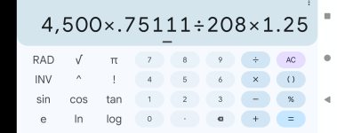
Just remember .75111 when going from 240 rated on a 208 system using single phase or 75%.
You can also use .86666 of the name plate current. Remember this for the element only no motors etc.
Now to get to these easy to remember numbers.
208/240= .86666
(208/240)^2=.7511
the ^ symbol in a squared function or .86666*.86666= .751099
So using 75% of the element in Watts
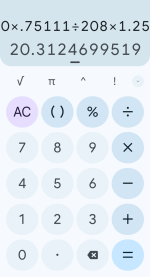
4500 w @ 240 v= 4500*.75111
The new Watts in power is 3379.95 watts
3379.95/ 208volts =16.24975 amps
Now the 4500 w.@ 240
4500/240= 18.75.amp.
18.75*.86666= 16.24975 amps
240 to 208 single phase
So 75% of the element In watts or 86% of the amps.
Or do the whole ohms law thing
Hope this helps.
Of courseCan you share a link.
Most use the name plate that comes with the water tank.
Gotcha. That’s a good rule of thumb thank you.Hope this helps.
Tulsa Electrician
Senior Member
- Location
- Tulsa
- Occupation
- Electrician
Thanks you sirYour welcome.
Pics of the easy way

I will also say Ryan Jackson is the best person to learn from. He puts out absolute GOLD for free. Mike Holt seemed like the man back in the day but it’s hard for me to follow him and his panel sometimes and his books and dvds are to expensive for me (can’t find them on eBay much either). I can’t follow much of Paul Abernathy or dustin stelzer either.
herding_cats
Senior Member
- Location
- Kansas
- Occupation
- Mechanical Engineer
Ohm's law only applies to loads (resistive) that have a power factor of 1. Like in a motor load, with a PF of .87 for example, using Ohm's law isn't accurate. Resistive loads like an incandescent light bulb, baseboard heater etc. apply and can be accurate.is anyone here an electrician or are you all engineers?
LarryFine
Master Electrician Electric Contractor Richmond VA
- Location
- Henrico County, VA
- Occupation
- Electrical Contractor
Pinnie, I'm serious about trying to explain what you're having trouble with.
For example, do you understand why the current "leads" the voltage in a capacitor?
For the most part, simple Ohm's Law works adequately when doing electrical math.
We tend to ask questions before answering, because we want to answer accurately.
All to often, the answer is, "It depends."
For example, do you understand why the current "leads" the voltage in a capacitor?
For the most part, simple Ohm's Law works adequately when doing electrical math.
We tend to ask questions before answering, because we want to answer accurately.
All to often, the answer is, "It depends."
I would be guessing. I understand a capacitor is two plates of semiconductor (i believe) each of which store oppositely charged ions. We use them for many things. The use that comes to mind is smoothing ac waveform when rectifying. Do I understand why the current leads voltage in a capacitor? No. You could’ve said voltage leads in a capacitor and I would say sounds good. The “why” has not clicked. i know just based off memorization that inductors have the opposite effect of capacitors in which lags which.For example, do you understand why the current "leads" the voltage in a capacitor?
that’s good enough for me. I just want to have safe installations.For the most part, simple Ohm's Law works adequately when doing electrical math.
Of course. Big questions have prerequisites.We tend to ask questions before answering, because we want to answer accurately.
no free lunches eh?All too often, the answer is, "It depends."
junkhound
Senior Member
- Location
- Renton, WA
- Occupation
- EE, power electronics specialty
Scanned this whole thread out of curiousity.
Nobody yet mentioned complex numbers
If you are not familiar with complex numbers, simply stay with dc for ohms law.
Nobody yet mentioned complex numbers
If you are not familiar with complex numbers, simply stay with dc for ohms law.
That is way on down the line. Bringing up complex numbers at this stage would really muddy the water. I think a conceptual understanding, an intuition, makes more sense right now than i and j and square roots.Scanned this whole thread out of curiousity.
Nobody yet mentioned complex numbers
If you are not familiar with complex numbers, simply stay with dc for ohms law.
- Occupation
- Licensed Electrician
You asked a question that only matters to engineers.is anyone here an electrician or are you all engineers?
I never studied theory but I have a good understanding of it and I never paid for a single class to learn it. I was lucky to have an above average journeyman. Asking questions here is the best way to learn it if that resource is lacking for you. The problem with most books is they want you to start with the atom and work your way up. There's a reason I never learned anything in school and the hardest three years of my life were 4th grade. If you can do basic Ohms law calcs and understand how a series and parallel circuit work that's all you need to get started.Not to sound lazy, but how much effort versus return do you think is there. I am maybe a third through mikes theory book and it feels like a lot of brain power to learn. Plus the theory well is deep, how much theory knowledge do I need? There’s only so many hours in the day. I’m more than capable of mastering theory, but I don’t think I want to be an engineer. I’m leaning towards focusing on studying business. I’m weak there.
A good grasp of electrical theory is important to being an above average electrician, but I got to be a way better electrician by learning circuitry, hand/off/auto switches, remote start/stop, playing with relays and making some sense of schematics than I ever did learning obscure ohms and three phase calculations. You'll never need to calculate impedance to get through a day at work.
petersonra
Senior Member
- Location
- Northern illinois
- Occupation
- Semi-retired engineer
Ohms law works for all circuits. The math is just easier for resistive circuits.The load profile matters.
Ohms law works for purely resistive loads.
Motors as an example are a constant power load so ohms law will not provide an accurate output.
Sent from my iPhone using Tapatalk
LarryFine
Master Electrician Electric Contractor Richmond VA
- Location
- Henrico County, VA
- Occupation
- Electrical Contractor
Allow me to try. Nothing as exotic as semiconductors. Physically, a capacitor is two sheets of aluminum foil separated by a sheet of waxed paper, rolled into a cylinder. Electrically, it behaves like a high-current rechargeable battery with a ridiculously short charge/discharge cycle.I would be guessing. I understand a capacitor is two plates of semiconductor (i believe) each of which store oppositely charged ions. We use them for many things. The use that comes to mind is smoothing ac waveform when rectifying. Do I understand why the current leads voltage in a capacitor? No. You could’ve said voltage leads in a capacitor and I would say sounds good. The “why” has not clicked. i know just based off memorization that inductors have the opposite effect of capacitors in which lags which.
Imagine a capacitor in series with a plain load, like a resistor, fed by an AC source. You can picture an AC sine wave, right? Okay, let's start the wave at 0v and begin ramping the voltage towards V+. Even though the voltage is still very low, the capacitor is charging at a high rate.
As the voltage wave settles at its peak, the capacitor is fully charged, so almost no current is passing through it, or the load. A the voltage starts to fall back towards 0v, the capacitor starts discharging, so its current rises, peaking as the voltage passes through 0v on its way toward V-.
As the negative peak is reached, the capacitor charges in the opposite direction until its current again drops to minimal. And again, as the voltage approaches 0v on its way towards +, the current approaches the peak, bringing us back to where we started.
Thus, the peak current through a capacitor occurs 90 degrees ahead of the peak voltage. With a purely-capacitive load, the entire current is fully 90 degrees leading. With a mixed load, the aggregate current is somewhere between 90 and 0 degrees leading.
Without going into detail about stored magnetism, etc., an inductor has the opposite effect, in that it resists change in the current, so it "charges and discharges," but the current tries to maintain despite the voltage dropping toward 0v, so the current peak follows.
The basic reason all this matters is, besides carrying the current that the load is converting into useful work, the conductors supplying the load also have to carry the wasteful charging and discharging current, so the entire electrical system must be sized to compensate.
Capacitance and inductance are collectively known as reactance, or reactive impedance. Impedance is made of resistance and reactance. The total power depends on the current through the total impedance, while the apparent power depends on the useful current.
The ratio of total power (expressed in volt/amps) to apparent power (expressed in watts) is known as the power factor, and is always 1.0 or lower. Capacitance and inductance can be used to counteract each other, which is called power-factor correction, or mitigation.
When power-factor correction is used, only the conductors (and equipment) between the load and the correction device need to be sized for the total power. This can save on installation and energy-bill costs, especially for industrial customers that pay more for poor power factors.
I hope that's enough to absorb for now. I have written a few other ditties, inducing one explaining how a neutral works.
Got itAllow me to try. Nothing as exotic as semiconductors. Physically, a capacitor is two sheets of aluminum foil separated by a sheet of waxed paper, rolled into a cylinder. Electrically, it behaves like a high-current rechargeable battery with a ridiculously short charge/discharge cycle.
Got it. Just the properties of the physical components of the capacitor cause it to charge at a high rate at “lower” voltages correct?Imagine a capacitor in series with a plain load, like a resistor, fed by an AC source. You can picture an AC sine wave, right? Okay, let's start the wave at 0v and begin ramping the voltage towards V+. Even though the voltage is still very low, the capacitor is charging at a high rate.
Is the capacitor stopping the flow current in a series circuit?As the voltage wave settles at its peak, the capacitor is fully charged, so almost no current is passing through it, or the load.
This is the 90 degrees out of phase as you describe in a purely capacitive circuit.A the voltage starts to fall back towards 0v, the capacitor starts discharging, so its current rises, peaking as the voltage passes through 0v on its way toward V-.
Gotcha. The capacitor’s plates swap charge polarity during positive and negative parts of the cycle.As the negative peak is reached, the capacitor charges in the opposite direction until its current again drops to minimal. And again, as the voltage approaches 0v on its way towards +, the current approaches the peak, bringing us back to where we started.
GotchaThus, the peak current through a capacitor occurs 90 degrees ahead of the peak voltage. With a purely-capacitive load, the entire current is fully 90 degrees leading. With a mixed load, the aggregate current is somewhere between 90 and 0 degrees leading.
This I need to study more. I used to think inductance/inductors only worked through electromagnetic induction (no direct connection) but I’ve since learned inductors are in series, with directly continuity, at least in electronics. I know there’s magnetic induction at play as well as direct continuity in many cases as well (transformer). I am weak here.Without going into detail about stored magnetism, etc., an inductor has the opposite effect, in that it resists change in the current, so it "charges and discharges," but the current tries to maintain despite the voltage dropping toward 0v, so the current peak follows.
This I understand. The terms in still trying to memorize but the concepts I get. Power factor is the ratio of apparent to real power. This matters because the worse your power factor, the more you pay for useful electricity. The power required to “fill” the circuit vs the power doing useful work. How to measure reactance and impedance are beyond me at this point.The basic reason all this matters is, besides carrying the current that the load is converting into useful work, the conductors supplying the load also have to carry the wasteful charging and discharging current, so the entire electrical system must be sized to compensate.
Capacitance and inductance are collectively known as reactance, or reactive impedance. Impedance is made of resistance and reactance. The total power depends on the current through the total impedance, while the apparent power depends on the useful current.
The ratio of total power (expressed in volt/amps) to apparent power (expressed in watts) is known as the power factor, and is always 1.0 or lower. Capacitance and inductance can be used to counteract each other, which is called power-factor correction, or mitigation.
When power-factor correction is used, only the conductors (and equipment) between the load and the correction device need to be sized for the total power. This can save on installation and energy-bill costs, especially for industrial customers that pay more for poor power factors.
Yes that’s very helpful and right at my understanding level. Thank you.I hope that's enough to absorb for now. I have written a few other ditties, inducing one explaining how a neutral works.