electrofelon
Senior Member
- Location
- Cherry Valley NY, Seattle, WA
- Occupation
- Electrician
Hey guys, this is for an "industrial control transformer". What are terminals 7 and 8? When I energized the windings, I get about 15 volts between 2 and 7. Is there another small winding in there to give you 12ish volts in case you need it? Is that "a thing" on some control transformers? I don't do much control work, but I don't recall seeing such a thing before and I can't find any mention of it in the instructions or schematics, just the picture in the attached diagram.
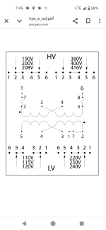
 . The voltage I was reading was just phantom voltage. Took me a little while to figure out it didn't have taps also. At first it looks like it with those different voltages and the "extra" terminals.