Yeah I was just trying to guess why the RR would want a single phase vs a regular split phase?If the service is actually for the railroad my guess would be it has more to do with the nearby grade crossing arms and lights than for signals for trains. Agree with zbang that they would not put 60hz AC power directly on the track.
You are using an out of date browser. It may not display this or other websites correctly.
You should upgrade or use an alternative browser.
You should upgrade or use an alternative browser.
What type of railroad three phase delta with only two conductors did I observe?
- Thread starter mdlueck
- Start date
zbang
Senior Member
- Location
- Roughly 5346 miles from Earls Court
...."split phase" is single phase...
There are limited instances where there is 60Hz power on the track as a grounded conductor, but those are 60Hz traction power systems, like the New Haven-Boston part of the North East Corridor.
BTW and going into the weeds here-
IIRC the original New Haven RR power system was 25Hz traction with 60Hz signal and track circuits. It also derived the power system from wye-connected generation where one leg is grounded as a delta would be and the "neutral point" left floating. All that pre-WW1.
jaggedben
Senior Member
- Location
- Northern California
- Occupation
- Solar and Energy Storage Installer
No idea. Are we sure it's not 480V single phase? My guess is the 3 phase sticker used to be correct.Yeah I was just trying to guess why the RR would want a single phase vs a regular split phase?
Could very well be a 480 pot.No idea. Are we sure it's not 480V single phase? My guess is the 3 phase sticker used to be correct.
Well @mdlueck looks like we'll need another MH forums mandated site investigationNo idea. Are we sure it's not 480V single phase? My guess is the 3 phase sticker used to be correct.
mdlueck
Member
- Location
- Michigan, USA
- Occupation
- Sr. IT Architect / Engineer
And what would I be seeking to observe and photograph?Well @mdlueck looks like we'll need another MH forums mandated site investigation
I have not seen such small around transformer pots for 480v output.
The 480v output with this utility company are larger around tubs, and frequently have additional heat fins on the sides.
This pole utility transformer looks like a standard 120/240v tub.
I am thankful,
Michael Lueck
Fred B
Senior Member
- Location
- Upstate, NY
- Occupation
- Electrician
Likely system was changed to single phase at some point. Had an old building that still had the CT metering setup on the mast and the old meter enclosure but was changed to 120/240 1P Still had the extra leg coming out of the weather head but not connected.
Birken Vogt
Senior Member
- Location
- Grass Valley, Ca
And what would I be seeking to observe and photograph?
I have not seen such small around transformer pots for 480v output.
The 480v output with this utility company are larger around tubs, and frequently have additional heat fins on the sides.
This pole utility transformer looks like a standard 120/240v tub.
I am thankful,
Michael Lueck
I was on vacation and observed two transformers on a pole near some railroad facility.
The catch was there were only 2 wires on the pole so not 3 phase.
I was able to use binoculars to observe the data plate of the tx and it said 120/240 per tx but they were wired with outside bushings connected only, as in your photo. And both tx in series.
So in that case, the utility was sending 1ph 480 direct to the RR.
kwired
Electron manager
- Location
- NE Nebraska
- Occupation
- EC
Even if it is, where does the three phase mentioned on the label come into play?I think its something like this:
View attachment 2578110
Which could be accomplished like this:
View attachment 2578111
I could not make out any of the stickers other than the transformer label but if your referring to theEven if it is, where does the three phase mentioned on the label come into play?
my guess is a standard 'single phase' utility meter really needs split phase or '120V to ground', so to meter a 240V or 480V single phase 2-wire service they would use a 'three phase delta' meter."3-Wire 3-Phase Delta Service and Metering"
I was just speculating why they would want a 240V line - neutral then 120V line to neutral as they clearly have a 5kva transformer?
480V service makes more sense, and in that case the 5kva is just making a 120/240 split phase for the crossing arm and the 480V 1-phase perhaps was give temp power for something or ?
I was kidding but a close up of the data plate on both the square D disconnects, voltage / phase number of poles would give a clueAnd what would I be seeking to observe and photograph?
If it's a '250V' class disconnect then it eliminates a 480V single phase 2-wire service and confirms a 240v single pahse 2-wire. If its 600V class then we still are guessing.
Side note it would be cool to have a thread (or more threads like this) on here that is just 'Pictures of oddball services', with a nice shot of the transformer connections, as all I ever see the standard boring four 120/240 1-phase, 3-phase; 208/120 and 480/277, 240/120.
whatever this service is its not a common one no doubt about it and the photos are well done.
kwired
Electron manager
- Location
- NE Nebraska
- Occupation
- EC
Is common to see pole top banks of single phase transformers to derive multiphase supply, but how often do you see banks of padmount transformers to do this? Around here it has become more rare but there is still an occasional older installation around. Last one I remember being involved with was a 480/277 with three pad mount transformers. What was more common to see however was open delta configurations from two pad mounts.I could not make out any of the stickers other than the transformer label but if your referring to the
my guess is a standard 'single phase' utility meter really needs split phase or '120V to ground', so to meter a 240V or 480V single phase 2-wire service they would use a 'three phase delta' meter.
I was just speculating why they would want a 240V line - neutral then 120V line to neutral as they clearly have a 5kva transformer?
480V service makes more sense, and in that case the 5kva is just making a 120/240 split phase for the crossing arm and the 480V 1-phase perhaps was give temp power for something or ?
I was kidding but a close up of the data plate on both the square D disconnects, voltage / phase number of poles would give a clue
If it's a '250V' class disconnect then it eliminates a 480V single phase 2-wire service and confirms a 240v single pahse 2-wire. If its 600V class then we still are guessing.
Side note it would be cool to have a thread (or more threads like this) on here that is just 'Pictures of oddball services', with a nice shot of the transformer connections, as all I ever see the standard boring four 120/240 1-phase, 3-phase; 208/120 and 480/277, 240/120.
whatever this service is its not a common one no doubt about it and the photos are well done.
mdlueck
Member
- Location
- Michigan, USA
- Occupation
- Sr. IT Architect / Engineer
I was kidding but a close up of the data plate on both the square D disconnects, voltage / phase number of poles would give a clue
If it's a '250V' class disconnect then it eliminates a 480V single phase 2-wire service and confirms a 240v single pahse 2-wire. If its 600V class then we still are guessing.
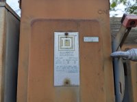
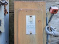
Here they are... both 480v and 600v are specified.
I suppose the disconnect rated at 100 amp heads to the signal box controlling the powered switch and the approach signals.
And suppose the 30 amp heads to the signal box controlling the crossing signals.
I am thankful,
Michael Lueck
Attachments
Here they are... both 480v and 600v are specified.
I suppose the disconnect rated at 100 amp heads to the signal box controlling the powered switch and the approach signals.
And suppose the 30 amp heads to the signal box controlling the crossing signals.
If it is a 480V service then I'd wager both the crossing arm and the signal box are running of the 120/240 split phase transformer.
Seems like railroad track switches would use a 20V or 24V DC motor with a gear box, possibly up to 120VDC, but not 480V. As it would be need to be capable of running off of batteries. So I doubt they would send 480V 1-phase 'end grounded' to a signal box or shack.
I got curious and looked up the rail switches and all I found were DC ones like this:
zbang
Senior Member
- Location
- Roughly 5346 miles from Earls Court
I'd have to dig out some old docs, but I recall there were AC switch machines for use on the AC-powered electric railroads. (IIRC the London Underground still has some pneumatic-powered "points machines" although the valves are electric. There used to be an air line running through the tunnels and each station, even some of the turnstiles used air.)