Bigbri0104
Member
- Location
- New Jersey
- Occupation
- Student
Hello Everyone,
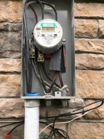
I'm working on a job that entails installing a 24 KW Generac automatic natural gas generator. The electrical service to the home is a 300-amp underground service with two 150-amp main breaker panels inside the basement, fed off a double lugged electrical meter. The service was installed prior to NEC 2020 code cycle. We are only installing one Automatic transfer switch, converting one main panel to a feeder panel, and updating the grounding and bonding system.
I already contacted the electric inspector and received the green light to mount our 150-amp automatic transfer switch inside the basement without installing it outside as an "Emergency Disconnect. The inspector also wanted to ensure the electrode system was updated. During our conversation about grounding and bonding, he wanted to make sure that the installation included inversible crimps, if I were to utilize the existing 1/0 common grounding electrode.
1st question - Does table 310.12 play into the initial installation, or must the SEU cable be sized to a min of 150 amp for each service panel that was installed? Table 310.12 was not used in the 2017 code cycle I think, which was around the time this house was built. However, for my own education would the electrician install 2/0 AL SEU cable or 3/0 AL SEU cable to each service panel.
2nd question - 250.64 (C) states the grounding electrode shall be installed in one continuous length without a splice or joint. If necessary, splices or connections shall be made as permitted in (1) though (4).
- Does this allow the electrician to install one large continuous wire by daisy chaining it through both service panels as shown in the picture below, Or must you follow the language in 250.64 (D) because of the charging language stating multiple disconnecting means in separate enclosures?
- My other question pertains to 250.64 (D) (2). This sub section states the electrician is allowed to install one continuous electrode from one service panel/service
disconnect based on the size of the largest ungrounded conductor in the enclosure, and terminate to let's say a water pipe, then install another continuous electrode from the second service panel/service disconnect enclosure to the same water pipe. The reason for the electrode example is because there is one present at the property. Am I reading this and interrupting it correctly?
Thanks,
Brian