You are using an out of date browser. It may not display this or other websites correctly.
You should upgrade or use an alternative browser.
You should upgrade or use an alternative browser.
SDS
- Thread starter pedro1200
- Start date
- Location
- Illinois
- Occupation
- retired electrician
Picture is poor quality, but I don't see an issue. What do you think is wrong?
hillbilly1
Senior Member
- Location
- North Georgia mountains
- Occupation
- Owner/electrical contractor
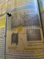
Are you talking about where the black arrow is pointing? That is the primary,
- Location
- New Jersey
- Occupation
- Journeyman Electrician (retired)
This is from the 2011 NECH but appears to be the same as the OP. Everything looks correct. The conductor between the transformer grounding terminal and the ground terminal in the other enclosure is a SSBJ.

Im talking about the sbj. Whats labeled here as a sbj imo is simply a bonding jumper . The sbj is the connection from secondary winding. Am i incorrect?This is from the 2011 NECH but appears to be the same as the OP. Everything looks correct. The conductor between the transformer grounding terminal and the ground terminal in the other enclosure is a SSBJ.
View attachment 2582559
- Location
- New Jersey
- Occupation
- Journeyman Electrician (retired)
That SBJ or system bonding jumper is correct in the graphic. Look at the definition in Article 100.Im talking about the sbj. Whats labeled here as a sbj imo is simply a bonding jumper . The sbj is the connection from secondary winding. Am i incorrect?
- Location
- Illinois
- Occupation
- retired electrician
The location of the system bonding jumper is up to the installer or designer...it can be in the transformer, or it can be in the first OCPD but not in both.ike holts illustrations show the sbj from the transformer winding to ground bar
- Location
- New Jersey
- Occupation
- Journeyman Electrician (retired)
Assuming that what you're calling the winding is actually the X0 he's correct.Im not saying is wrong but mike holts illustrations show the sbj from the transformer winding to ground bar
Yes i understand that. I was confused on this illustration labeling of sbj not the locationThe location of the system bonding jumper is up to the installer or designer...it can be in the transformer, or it can be in the first OCPD but not in both.
Yes thats correct the xoAssuming that what you're calling the winding is actually the X0 he's correct.
- Location
- New Jersey
- Occupation
- Journeyman Electrician (retired)
So when you're installing the SBJ in the transformer it goes from the X0 to the terminal provided for all of the grounding and bonding connections or from the neutral to the case of the transformer as shown in the graphic. IMO the labeling of the neutral in the graphic is confusing. This is where the graphic that I posted may differ from the OP.Yes thats correct the xo
Thank you i agree.So when you're installing the SBJ in the transformer it goes from the X0 to the terminal provided for all of the grounding and bonding connections or from the neutral to the case of the transformer as shown in the graphic. IMO the labeling of the neutral in the graphic is confusing. This is where the graphic that I posted may differ from the OP.
- Location
- New Jersey
- Occupation
- Journeyman Electrician (retired)
I cannot tell from you photo but is the 2020 graphic different from the 2011 graphic that I posted? If I remember correctly between those two code cycles the NEC added a requirement for a factory installed terminal in the transformer for bonding and grounding purposes.Thank you i agree.
They seem to be the sameI cannot tell from you photo but is the 2020 graphic different from the 2011 graphic that I posted? If I remember correctly between those two code cycles the NEC added a requirement for a factory installed terminal in the transformer for bonding and grounding purposes.