120/208 3-ph, 4W panelboard amps on A phase?

Status
Not open for further replies.

GoldDigger

Moderator
Staff member
Location
Placerville, CA, USA
Occupation
Retired PV System Designer
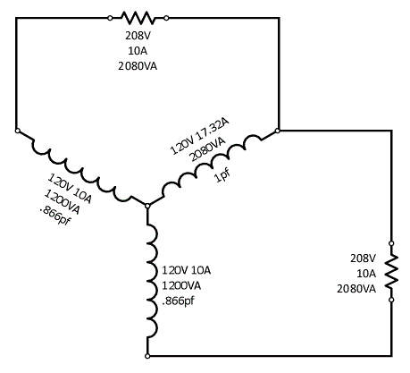
The windings in the transformer are never 120V at the same instance in time due to the phase shift. Their maximum potential difference, rms, is 208V at any given point in time.

I.E. 120sin (x) - 120sin (x-120) has a max value of 208, your picture is misleading.

Your picture should have 103.9V, 10A, and 1039VA on each transformer coil the moment in time the load is experiencing 208V .
No. The component of the line to neutral voltage that is in phase with the line current will be half of 208. But the magnitude of the voltage will be greater, namely 120V.
That is why the comment was made that the PF seen by each winding of a wye source will not be the same as the load PF.
 

quantum

Senior Member
Location
LA
No. The component of the line to neutral voltage that is in phase with the line current will be half of 208. But the magnitude of the voltage will be greater, namely 120V.
That is why the comment was made that the PF seen by each winding of a wye source will not be the same as the load PF.

I was referencing the image in post #115 specifically, which has no load on the neutral.
 

Smart $

Esteemed Member
Location
Ohio
The windings in the transformer are never 120V at the same instance in time due to the phase shift. Their maximum potential difference, rms, is 208V at any given point in time.

I.E. 120sin (x) - 120sin (x-120) has a max value of 208, your picture is misleading.

Your picture should have 103.9V, 10A, and 1039VA on each transformer coil the moment in time the load is experiencing 208V .
That's not quite right either.

My version:
Two%20L-L%20loads.gif
 

quantum

Senior Member
Location
LA
Makes absolutely no difference.
When the voltage across the L-L load is 208 the L-N voltage will be 120 whether there is net current in the neutral or not.

Not on both coils at the same instance in time. Maybe I need to read more posts on this thread, I'm commenting specifically on the picture in post #115.

The claim was that the VA on the transformer windings was different than that of the load. However, the picture simply shows the max values for both windings and the load. The two windings will not actually be 120V at the same instance in time... ever.
 

Smart $

Esteemed Member
Location
Ohio
Not on both coils at the same instance in time. Maybe I need to read more posts on this thread, I'm commenting specifically on the picture in post #115.

The claim was that the VA on the transformer windings was different than that of the load. However, the picture simply shows the max values for both windings and the load. The two windings will not actually be 120V at the same instance in time... ever.
120V is an RMS "average" over time, They are both always a nominal 120VRMS when energized. We already realize they are out of phase with 208V between lines.

Better to stick with conventional wisdom. :happyyes:
 

GoldDigger

Moderator
Staff member
Location
Placerville, CA, USA
Occupation
Retired PV System Designer
Not on both coils at the same instance in time. Maybe I need to read more posts on this thread, I'm commenting specifically on the picture in post #115.

The claim was that the VA on the transformer windings was different than that of the load. However, the picture simply shows the max values for both windings and the load. The two windings will not actually be 120V at the same instance in time... ever.

A valid point, and reinforcing for us the problems which can arise when thinking of phasors as simple vectors. :)

It is correct that at the time that the voltage across the load is 208V the instantaneous voltage on the two 120V windings is ~104V and the two are exactly opposite in polarity.

Except that is not exactly what is happening either. The voltage peak on the 208V load is not 208V because 208 is the RMS value of the voltage.
And the voltage on the two windings is not properly 104V RMS but rather the peak value corresponding to a 104V RMS waveform.

For the sake of simplicity, we could agree to speak as if the peak voltage was the RMS value, and if everyone could keep that straight it might work.

The "amplitude" vectors whose length is the RMS value are easier to work with, but at the risk of putting too much stress on the spatial nature of the vectors and losing the time dependence of the actual waveform.

Whatever approach is taken, it needs to be consistently followed by all, or endless circular discussions will result.

Bottom line: The current in each wye winding which corresponds to a single L-L load will not be in phase with the winding's voltage to ground.
The net current in the common leg, OTOH, will be in phase with that leg's voltage. Once you balance the loads on the three phases, the product of line current and line voltage times three is equal to the product of load current and load voltage times three. And if you try to work with the combination of line current and L-L voltage you end up with a factor of sqrt(3) coming in instead.
 
Status
Not open for further replies.
Top