
- Location
- Bremerton, Washington
- Occupation
- Master Electrician
I read many posts on PVs and see reference to 120% for bus and disconnect sizing. What is the reasoning for 120%?
There is no rationale in particular. The committee writing the code thought that a bus can take more than 100% of its rating if it's fed from both ends, and the consensus was that 125% is too much and 115% isn't enough. So, 120%.I read many posts on PVs and see reference to 120% for bus [the reference to disconnects removed because the 120% rule doesn't have anything to do with discos] sizing. What is the reasoning for 120%?

Can you expand on that with a pointer to the product/technical info?I mean, if Enphase can take Eaton manufacturered panelboards and list them in assemblies for specific multiple source scenarios,
The Enphase Enpower switch contains a 200A panelboard that is allowed per the instructions to have up to a 200A utility supply breaker, 80A PV breaker, 80A ESS breaker, and 200A load breaker, all connected at the same time. (There are relays for the PV and ES breakers, and also for a 40A autotransformer and 60A generator, but the latter two wouldn't be connected when the utility is connected. The PV and ES could be, with 128A flowing from them, as far as I know.)Can you expand on that with a pointer to the product/technical info?
Thanks,
Wayne
a apt explanation Car, the only thing i get confused with is>>>The short answer is, it is an industry compromise between the code making panel, the UL standards of panelboard manufacturing, and the solar industry trying to take as much credit as they can for Kirchhoff's current law as much as possible. There is no physical basis for why it is 120% specifically, of all possible numbers it can be.
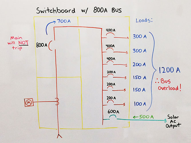
Panelboards are routinely loaded with breakers that add up to far greater than the busbar rating, and far greater than the main supply breaker. The underlying idea is that they don't all draw their full load at once. There still is a chance that they do, and the expectation is that the main breaker trips before the busbar or breakers overheat. When you are feeding a panelboard with a busbar rating of X amps from only one source, you simply install a main breaker of X amps, and you protect the busbar from overload.
Now suppose you want to introduce solar as a second source. If you use the same end as the main supply, then the current from both sources is additive. However, if you feed it from opposite end, that is when you get to take credit for the 120% rule, because current in opposite directions on the busbar is subtractive rather than additive.
From reasoning it through with Kirchhoff's laws, you might think it should be able to be a 200% rule, rather than a 120% rule. After all, if you feed a 200A panel with a 200A OCPD on both ends, no matter how you arrange the loads, it will never load any cross section of the busbar to more than 200A. However, the concern was that drawing 400A of current worth of heating in the branch breakers would be problematic, even if no cross section of the busbar ever sees more than 200A. The 120% limit for doing this was established as compromise on this issue, allowing you to backfeed up to 20% of the busbar rating on a panel with a matching main and bus. Or allowing you to reduce the main breaker, as long as the two sources add up to no greater than 120% of the bus. In 2014, they re-wrote the rule, so that it is no longer the PV breaker rating, but rather the factor that sizes the breaker, prior to rounding to a standard size.
The substance of this rule has been constant since 2014, but the code sections and subsections have been reorganized in just about every code cycle. This is why you consistently see people calling it "the 120% rule". It has always been somewhere in 705.12, but when you don't know which code version someone is using, it is easiest just to call it "the 120% rule".
He just means that current cannot flow both directions in a conductor simultaneously. For example, if you have a subpanel on a feeder from a main that is drawing 100A, then there is 100A flowing in the feeder, but if you connect 50A of PV in that subpanel (at the opposite end of the busbar from the main breaker, of course), then the current in the feeder is reduced to 50A.a apt explanation Car, the only thing i get confused with is>>>
because current in opposite directions on the busbar is subtractive rather than additive.
does this mean opposing ends of the sine wave?
~RJ~
As best I know, your first paragraph accurately describes the reality. That said there are also CTs to measure PV production and site consumption, and relays to disconnect the sources, so I can't say for sure that's not part of tue scheme.That is a bit weird. Does it support having 200A flowing in on the grid breaker, 64A flowing in on the PV, 64A flowing out on the ESS breaker to charge the ESS, and 200A flowing out to the loads? If so, that must have entailed some application specific temperature rise testing, I would expect.
Or does it have CTs to monitor the various current flows to limit the current in from the grid and the PV to 240A total? In that case, I would think it could be listed as a PCS and that would suffice.
When the ESS is not charging, there's no issue as the load breaker limits the bus current to 200A.
Cheers, Wayne
FWIW, Eaton CH panelboards from 150A to 225A all use 225A busbars.As best I know, your first paragraph accurately describes the reality. That said there are also CTs to measure PV production and site consumption, and relays to disconnect the sources, so I can't say for sure that's not part of tue scheme.
Perhaps an interesting tidbit to add is that the ESS cannot charge from the PV at 64A for the 3 hours that would make it 'continuous' per the NEC, because they would be full in 2.57 hours or less.
Also, now that I think about it, I'm not positive that the busbars aren't rated higher than 200A.
I read many posts on PVs and see reference to 120% for bus and disconnect sizing. What is the reasoning for 120%?
 www.purepower.com
well you might remember, years ago GGunn, the debut of the TSW inverter, something about it's ability to 'synch' with the poco, was a huge NRTL fight, but they won outHe just means that current cannot flow both directions in a conductor simultaneously. For example, if you have a subpanel on a feeder from a main that is drawing 100A, then there is 100A flowing in the feeder, but if you connect 50A of PV in that subpanel (at the opposite end of the busbar from the main breaker, of course), then the current in the feeder is reduced to 50A.
We once encountered an inspector who insisted that the current in the feeder would be 150A. That was frustrating.
, has this something to do with this.....?a apt explanation Car, the only thing i get confused with is>>>
because current in opposite directions on the busbar is subtractive rather than additive.
does this mean opposing ends of the sine wave?
~RJ~


I don't remember that, but what I was talking about is basic electrical theory. Current can only flow in one direction at a time through a conductor.well you might remember, years ago GGunn, the debut of the TSW inverter, something about it's ability to 'synch' with the poco, was a huge NRTL fight, but they won out
and so i'm confused.....
~RJ~